A Mechanical Manual High Space Lighting Control Device

A control device and high-space technology, which is applied in the direction of lighting devices, lighting auxiliary devices, lighting device components, etc., can solve the problems of narrow space in corridors and stairwells, scattered lighting layout, heavy weight, etc., to improve erection efficiency, Effect of Mechanical Adjustment Process Stabilization

Active Publication Date: 2018-06-19
BEIJING TIANHENG CONSTR
View PDF4 Cites 0 Cited by
  • Summary
  • Abstract
  • Description
  • Claims
  • Application Information

AI Technical Summary

Problems solved by technology

The maximum safe operating height of the high-altitude ladder is 5m, and after the high-altitude lamps are installed, the height is greater than 5m, which exceeds the safe height and poses a safety hazard
The operation of the lift car is very convenient, and it can be lifted and lowered freely, but the lift car is bulky and heavy, and it is inconvenient to move upstairs
However, some engineering stadiums are located on the third floor, and the space in the corridors and stairwells is relatively narrow, and the lift truck cannot be transported upstairs.
If the lift car is placed in the stadium, it will take up a lot of space, and the storage location is not considered in the design, and it will affect the use of the stadium
Steel frame channels are generally installed in steel structure venues with large areas and concentrated lighting installations. The stadium of this project is a reinforced concrete structure with a small area and scattered lighting layout. And the cost is high

Method used


Image

  • A Mechanical Manual High Space Lighting Control Device
  • A Mechanical Manual High Space Lighting Control Device
  • A Mechanical Manual High Space Lighting Control Device

Examples


Embodiment Construction

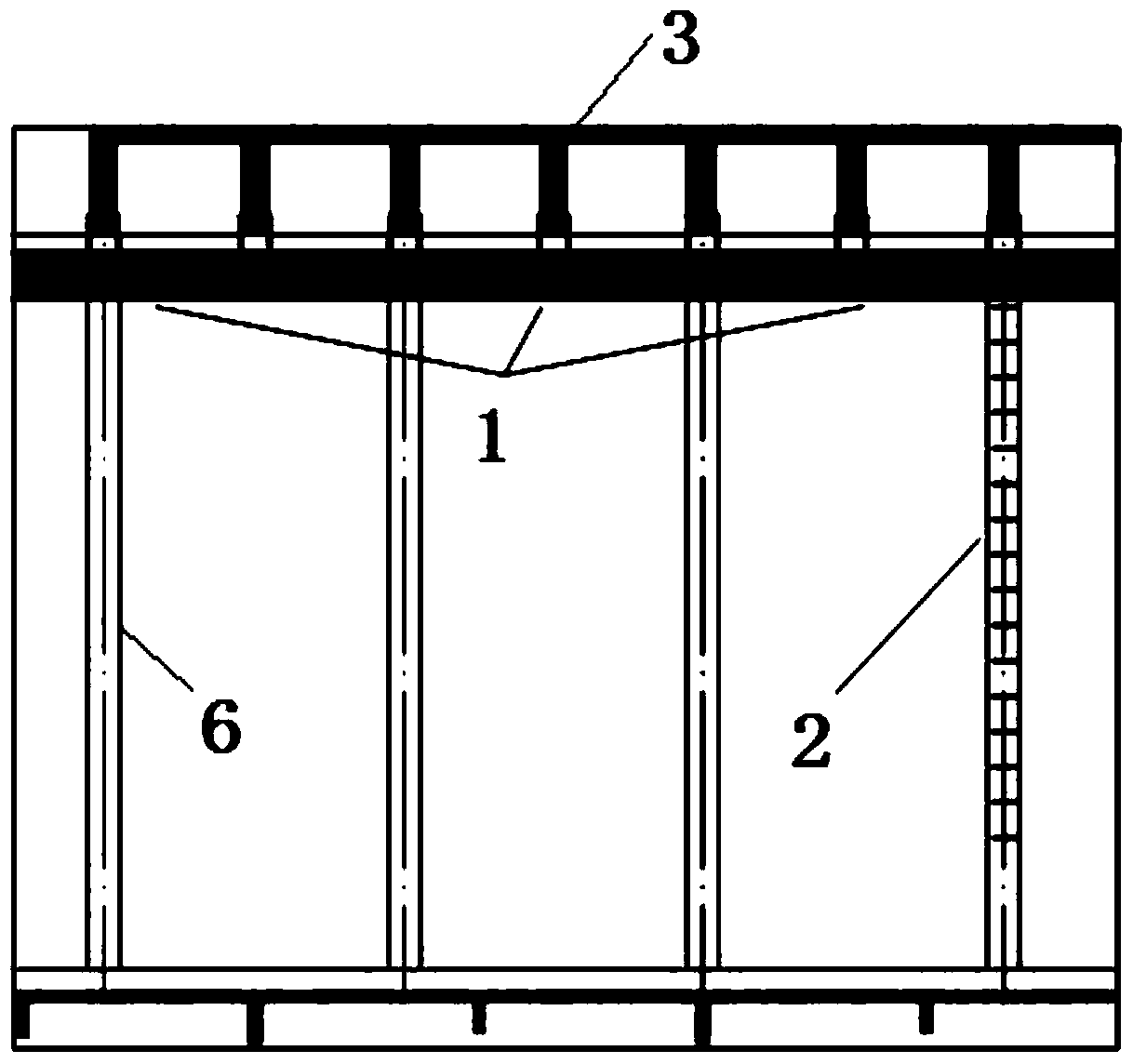
[0025] Such as figure 1 As shown, along the layout direction of each row of lamps, build a cantilever maintenance platform of about 0.8m against one side wall, and set up a ladder on the platform, which can be accessed from the ground.

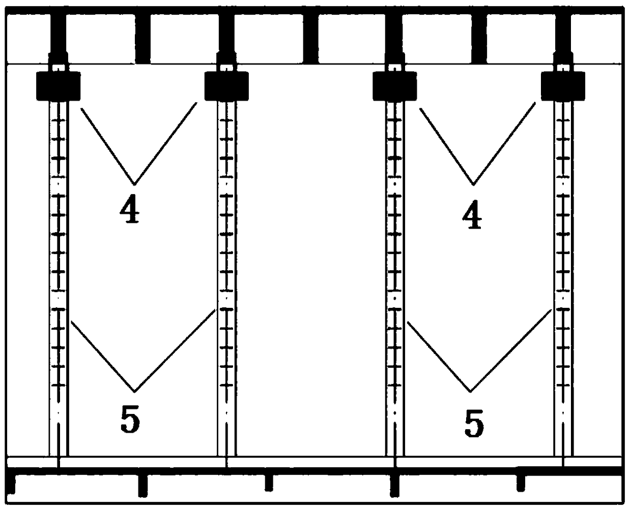
[0026] Such as figure 2 As shown, the maintenance platform can also be provided with a small maintenance platform on one side of each row of lamps, cantilevered on the wall and provided with a ladder.

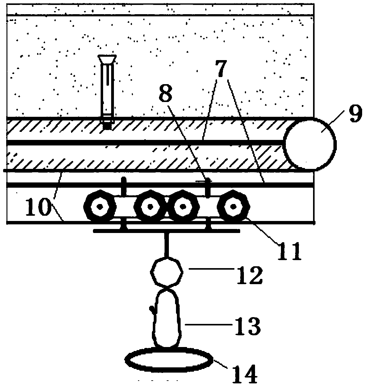
[0027] Such as image 3 Schematic diagram of the installation structure for lamps and track systems, such as Figure 4 Install the vertical structure diagram for the take-up system, such as Figure 5 Schematic diagram of the lateral structure for the installation of the take-up system.

[0028] A mechanical manual control device for high-space lamps, which includes a take-up and release system, a maintenance platform, a lamp and a track system.

[0029] The take-up and pay-off system is the adjustment control structure of the whole device...


PUM


Abstract

The invention discloses a mechanical manual overhead lamp control device. A wire winding and unwinding system is an adjusting and control structure of the whole device. An overhaul platform is a work face of the device. A lamp and rail system is an arranging framework structure of the whole device. A through-length platform is arranged on the side close to the wall. The arranging direction of the through-length platform is equal to that of lamps. The lamp and rail system is arranged on a structural beam in the arranging direction of the lamps. The wire winding and unwinding system is connected with the end of a steel wire rope. The lamps to be erected overhead can be made to be in a movable state through the wire winding and unwinding system, the overhaul platform and the lamp and rail system, and the positions of the lamps to be installed or erected can be adjusted at any time. Due to the manual rotating operation of a wire winding device, the steel wire rope is driven, one row of lamps are recycled to one end, the whole device adjusting process is stable, firm and accurate, and the erecting efficiency of the lamp can be effectively improved. According to the mechanical manual overhead lamp control device, overhauling on a fixed and simple operation platform can be achieved, and meanwhile restoring to normal positions can be rapidly achieved after all processes are completed.

Description

technical field [0001] The invention relates to a mechanical manual high-altitude lamp control device, which belongs to the technical field of high-altitude lamp erection. Background technique [0002] Tall spaces are often encountered in new buildings, such as gymnasiums, conference halls, etc., and their lamps are fixed at high altitudes. After the completion of the project, the user needs to replace and repair the lamps during the actual use. The high-altitude tools generally used are: 1) ladder; 2) elevator; 3) repair steel frame. The highest safe operating height of the high-altitude ladder is 5m, and after the high-altitude lamps are installed, their heights are all greater than 5m, which exceeds the safe height and poses a safety hazard. The operation of the lift car is very convenient, and it can be lifted and lowered freely, but the lift car is bulky and heavy, and it is inconvenient to move upstairs and use. However, some engineering stadiums are located on the t...

Claims


Application Information

Patent Timeline
Patent Type & Authority Patents(China)
IPC IPC(8): F21V21/38
CPCF21V21/38
Inventor 张鹏李康孟迪石飞郭旭
Owner BEIJING TIANHENG CONSTR
Why Eureka
Try Eureka