Automatic feeding device and method for evaporator
An automatic feeding and evaporator technology, which is applied in transportation and packaging, conveyor objects, etc., can solve the problems of low efficiency, high labor intensity, low degree of automation, etc., and achieve the effect of convenient installation, promotion of automation process, and simple structure.
- Summary
- Abstract
- Description
- Claims
- Application Information
AI Technical Summary
Problems solved by technology
Method used
Image
Examples
Embodiment 1
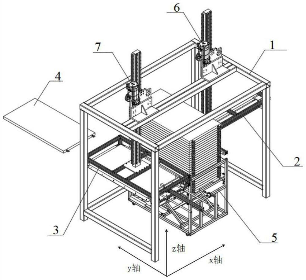
[0037] Please refer to the attached figure 1 The present invention provides an automatic feeding device for an evaporator, which is used for automatic feeding of the evaporator, so that the evaporator is automatically transferred from the tooling vehicle to the destination. In this application, the surface of the evaporator includes multiple fins, and special attention should be paid to the protection of the fins during the transmission process to ensure that the performance of the evaporator is not affected. The automatic feeding device specifically includes a support frame 1 and a horizontal pushing mechanism 2 and a vertical pushing mechanism 3 respectively located at both ends of the supporting frame 1; an evaporator 4 is placed between the horizontal pushing mechanism 2 and the vertical pushing mechanism 3, and the evaporator 4 can be stacked on the work truck 5.
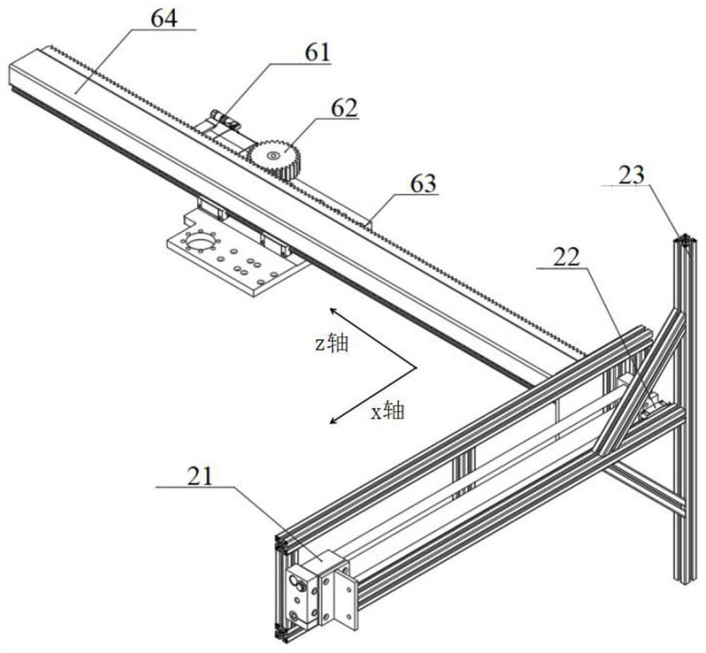
[0038] Please refer to the attached figure 2 , the horizontal pushing mechanism includes a pushing rod 23...
Embodiment 2
[0042] Please continue to see attached figure 2 , as a preferred embodiment, the horizontal push mechanism in the present application also includes a horizontal guide rail 22, the push rod 23 and the horizontal push cylinder 21 are respectively located at the two ends of the horizontal guide rail 22, and the horizontal push cylinder 22 is connected and drives The push rod 23 moves along the transverse guide rail 22 . When the moving range of the push rod along the x-axis is large, there may be a deviation in the direction during the movement, so that the evaporator cannot move forward in a straight line; the linear guide rail ensures that the moving direction of the push rod is always a straight line , and then smoothly push the evaporator into the loading frame.
[0043] The push rod 23 needs to push the evaporator 4 from the tooling truck 5 into the loading frame, and its range of motion is from the side of the tooling truck away from the loading frame to the side of the t...
Embodiment 3
[0046] As the top-layer evaporators are output in turn, the height of the evaporators in the tooling vehicle is constantly changing. In order to ensure that the push rod and the loading frame are on the same level as the evaporators to be transported, the present invention also needs to be provided with a lifting mechanism. structure. The structure used for lifting is divided into three situations. The first one is to lift the horizontal pushing mechanism and the vertical pushing mechanism in the feeding device, and the height of the evaporator remains unchanged. The second is to lift the evaporator, while the heights of the horizontal pushing structure and the vertical pushing mechanism in the feeding device remain unchanged. The third is to simultaneously adjust the evaporator, the horizontal push rod and the loading frame to be located on the same level as the evaporator to be transported.
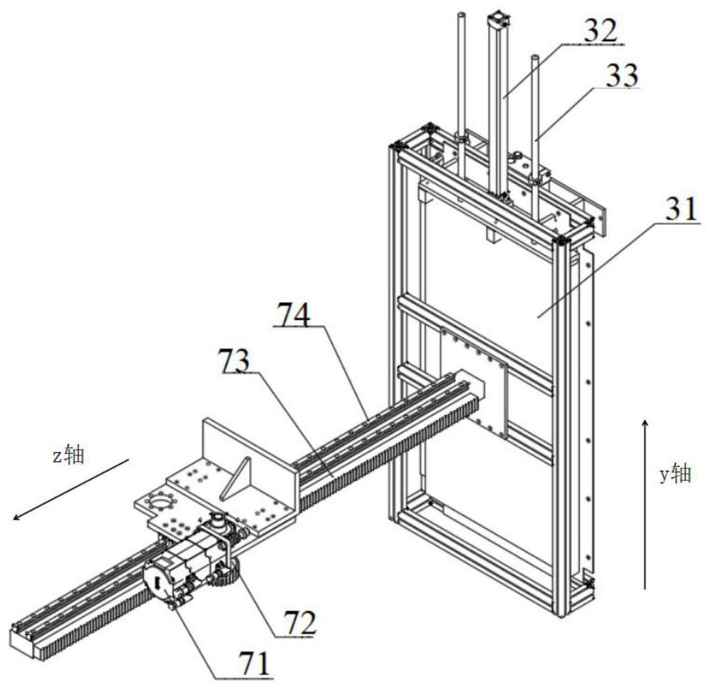
[0047] For the first case, the feeding device also includes a lifting mechanism, w...
PUM
 Abstract
Description
Claims
Application Information
 - R&D
- Intellectual Property
- Life Sciences
- Materials
- Tech Scout
- Unparalleled Data Quality
- Higher Quality Content
- 60% Fewer Hallucinations
Browse by: Latest US Patents, China's latest patents, Technical Efficacy Thesaurus, Application Domain, Technology Topic, Popular Technical Reports.
© 2025 PatSnap. All rights reserved.Legal|Privacy policy|Modern Slavery Act Transparency Statement|Sitemap|About US| Contact US: help@patsnap.com


