Unpowered vacuum chuck with automatic centering function

A technology of automatic centering and vacuum suction cups, applied in conveyors, conveyor objects, transportation and packaging, etc., can solve the problems of buffer collision between objects and supports, poor manual adjustment accuracy, and poor stability, etc. Accuracy, stable operation, and ingenious effects

Pending Publication Date: 2022-03-08
南通安泰机械有限公司
View PDF0 Cites 0 Cited by
  • Summary
  • Abstract
  • Description
  • Claims
  • Application Information

AI Technical Summary

Problems solved by technology

[0002] Vacuum suction cups, also known as vacuum slings, are one of the actuators of vacuum equipment. Generally speaking, it is the most economical and affordable method to use vacuum suction cups to grab products. Non-powered vacuum suction cups belong to the category of vacuum suction cups. The existing The unpowered vacuum suction cup is composed of a bracket, a control box, a suction cup, etc., and has a simple structure and low manufacturing cost; however, there are still certain defects in use. The centering of the size usually requires manual adjustment of the position of the suction cups on both sides. The accuracy of manual adjustment is relatively poor, resulting in insufficient stability during suction; Being able to position the item makes it easy to produce a certain buffer collision between the item and the support. In view of the above defects, we propose a non-powered vacuum suction cup with automatic centering function to solve the above problems

Method used


Image

  • Unpowered vacuum chuck with automatic centering function
  • Unpowered vacuum chuck with automatic centering function
  • Unpowered vacuum chuck with automatic centering function

Examples


Embodiment 1

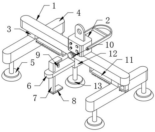
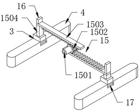
[0027] Such as figure 1 and figure 2 As shown, the present invention proposes a non-powered vacuum suction cup with automatic centering function, including a connecting rod 1 and a control box 2 connected to the upper end of the connecting rod 1, and the middle part of the lower end of the connecting rod 1 is connected with a suction cup 2 through a mounting base plate 12. 13. The inside of the connecting rod 1 is provided with a transmission adjustment mechanism 15. The transmission adjustment mechanism 15 includes two connecting rods 1504 slidingly connected to the lower surface of the connecting rod 1. The lower end of the connecting rods 1504 is connected to the moving rod 4 through the connecting block 3; The inside of the moving bar 4 is provided with a distance-adjusting mechanism 11, and the distance-adjusting mechanism 11 includes two guide blocks 1105 that are slidably connected to the lower surface of the moving bar 4, and the lower ends of the two guide blocks 110...

Embodiment 2

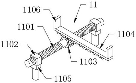
[0030] Such as figure 1 and image 3 As shown, the present invention proposes a non-powered vacuum chuck with automatic centering function. Compared with Embodiment 1, this embodiment also includes: the distance adjustment mechanism 11 includes a bidirectional adjustment screw 1101 that is rotatably connected to the moving rod 4 , the outer thread sleeve of the two-way adjusting screw 1101 is provided with two screw blocks 1102, and the two screw blocks 1102 are respectively fixedly connected with the upper ends of the two guide blocks 1105; The lower end is connected to a rack a1104 through a pair of fixed connecting plates 1106, and the rack a1104 is meshed with the corresponding transmission gear a1103 for transmission; the side surface of the moving rod 4 is provided with a rectangular slot 17, and the rack a1104 runs through the corresponding rectangular slot. Through slot 17, when the two moving rods 4 are close to each other, the two transmission gears a1103 are respec...

Embodiment 3

[0032] Such as Figure 1-3As shown, the present invention proposes a non-powered vacuum chuck with automatic centering function. This embodiment includes: a connecting rod 1 and a control box 2 connected to the upper end of the connecting rod 1. The middle part of the lower end of the connecting rod 1 passes through the installation base plate 12 The suction cup 2 13 is connected, and the inside of the connecting rod 1 is provided with a transmission adjustment mechanism 15. The transmission adjustment mechanism 15 includes two connecting rods 1504 that are slidably connected to the lower surface of the connecting rod 1. The lower end of the connecting rod 1504 is connected to a Moving bar 4; The inside of moving bar 4 is provided with distance-adjusting mechanism 11, and distance-adjusting mechanism 11 comprises two guide blocks 1105 that are slidably connected to the lower surface of moving bar 4, and the lower ends of two guide blocks 1105 are all provided with suction cups-...


PUM


Abstract

The invention relates to the technical field of vacuum chucks, in particular to an unpowered vacuum chuck with an automatic centering function. The unpowered vacuum suction cup mainly aims at solving the problems that an existing unpowered vacuum suction cup cannot be centered according to the size of an object when sucking the object, generally, the positions of suction cups on the two sides need to be adjusted through manual visual inspection, and consequently the stability is not good enough in the final sucking process; according to the technical scheme, the device comprises a connecting rod and a control box connected to the upper end of the connecting rod, a second suction cup is connected to the middle of the lower end of the connecting rod through a mounting bottom plate, a transmission adjusting mechanism is arranged in the connecting rod, and the transmission adjusting mechanism comprises two connecting rods slidably connected to the lower surface of the connecting rod in a penetrating mode; the lower end of the connecting rod is connected with a moving rod through a connecting block. The automatic centering vacuum chuck has the automatic centering function, the centering precision is improved through automatic adjustment, the suction effect can be guaranteed, and compared with an existing vacuum chuck, the technology is greatly improved.

Description

technical field [0001] The invention relates to the technical field of vacuum suction cups, in particular to an unpowered vacuum suction cup with an automatic centering function. Background technique [0002] Vacuum suction cups, also known as vacuum slings, are one of the actuators of vacuum equipment. Generally speaking, it is the most economical and affordable method to use vacuum suction cups to grab products. Non-powered vacuum suction cups belong to the category of vacuum suction cups. The existing The unpowered vacuum suction cup is composed of a bracket, a control box, a suction cup, etc., and has a simple structure and low manufacturing cost; however, there are still certain defects in use. The centering of the size usually requires manual adjustment of the position of the suction cups on both sides. The accuracy of manual adjustment is relatively poor, resulting in insufficient stability during suction; The object can be positioned so that a certain buffer collisi...

Claims


Application Information

Patent Timeline
Patent Type & Authority Applications(China)
IPC IPC(8): B65G47/91
CPCB65G47/91B65G2249/045
Inventor 张建张婷婷
Owner 南通安泰机械有限公司
Why Eureka
Try Eureka