
Clutch mechanism and power clutch control device and method

A clutch mechanism and control device technology, which is applied in the direction of clutches, magnetic drive clutches, non-mechanical drive clutches, etc., can solve the problems of processing machine tools that cannot flexibly control the transmission of energy, adverse effects on processing objects, and poor processing effects, etc., to achieve improved processing Yield, avoidance of adverse effects, reduction of operational risk and effects of manufacturing costs

Pending Publication Date: 2022-03-08
国焊(上海)智能科技有限公司
View PDF8 Cites 0 Cited by
  • Summary
  • Abstract
  • Description
  • Claims
  • Application Information

AI Technical Summary

Problems solved by technology

[0003] However, since the rotating mechanism is fixed to the main shaft, the energy transmitted by the machine tool to the processing object may be greater than the actual energy required during processing; when the processing is terminated or interrupted, the machine tool needs to disconnect the power source first, and then wait for the turning mechanism to However, the rotating mechanism still has a tendency to rotate under the action of inertia, causing the main shaft to deflect, which in turn drives the back-end parts to deflect, causing adverse effects on the processing object (such as serious deformation of the processing object) and destructive properties)
[0004] It can be seen from the above that the existing processing machine tools cannot flexibly control the energy transmitted to the processing object, resulting in energy loss and poor processing results

Method used


Image

  • Clutch mechanism and power clutch control device and method
  • Clutch mechanism and power clutch control device and method
  • Clutch mechanism and power clutch control device and method

Examples


Embodiment Construction

[0041] As mentioned in the background art, existing processing machine tools cannot flexibly control the energy transmitted to the processing object, resulting in energy loss and poor processing results.

[0042] In order to solve the above problems, the embodiment of this specification provides a clutch mechanism, which is located between the transmission mechanism and the rotation mechanism of the processing machine tool; wherein: the support component can be linked with the transmission mechanism, and the support component can be connected with the support component through the first transmission component. In linkage, the second transmission component can be rotatably connected to the support component, and the carried rotation mechanism can be isolated from the transmission mechanism through the second transmission component.

[0043] On the one hand, by controlling the engagement or separation of the first transmission part and the second transmission part of the clutch m...


PUM


Abstract

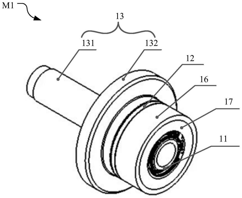
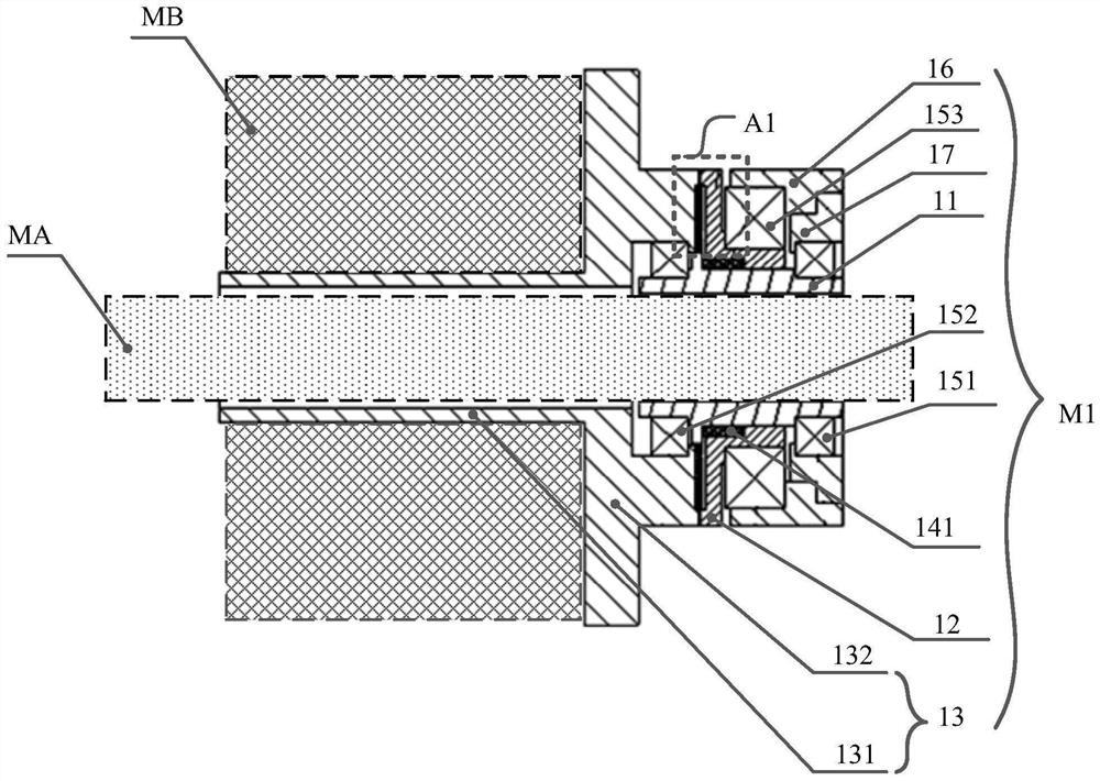
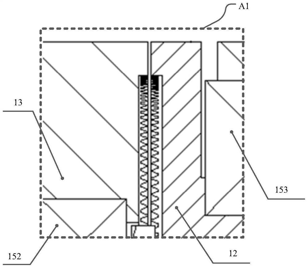
The embodiment of the invention provides a clutch mechanism and a power clutch control device and method.The clutch mechanism comprises the clutch mechanism, and the clutch mechanism comprises a supporting component, a first transmission component and a second transmission component; the supporting component is linked with the transmission mechanism; the first transmission part is linked with the supporting part and is connected with or separated from the second transmission part; and the second transmission part is rotatably connected with the supporting part and is suitable for bearing the rotating mechanism and isolating the rotating mechanism from the transmission mechanism. By adopting the scheme of the embodiment of the invention, the energy transmitted to the processing object can be flexibly controlled, and the energy efficiency, the processing quality and the processing yield are improved.

Description

technical field [0001] The embodiments of this specification relate to the technical field of mechanical manufacturing, and in particular to a clutch mechanism, a power clutch control device and a method. Background technique [0002] In the machining process, the main shaft of the processing machine tool is mainly used to transmit energy. It can receive power from a power source such as a power mechanism and drive the back-end parts (such as processing tools, fixtures, etc.) Forgings, weldments, etc.) for processing (such as forging, welding, etc.). In order to obtain more energy, the rotating mechanism can be fixed on the main shaft, the main shaft drives the rotating mechanism to rotate, and the power generated by the rotating mechanism acts against the main shaft, thereby increasing the energy transmitted from the main shaft to the rear-end parts, which can drive larger backend mechanism. [0003] However, since the rotating mechanism is fixed to the main shaft, the en...

Claims


Application Information

Patent Timeline
Patent Type & Authority Applications(China)
IPC IPC(8): F16D27/04F16D27/14
CPCF16D27/04F16D27/14
Inventor 朱建华夏春明彭虎王天波赵江龙王立人孙涛罗希玲
Owner 国焊(上海)智能科技有限公司
Learn More