Soft bullet continuous launching device of toy gun and toy gun comprising launching device

A launcher, toy gun technology, applied to spring guns, weapons without explosives, offensive equipment, etc., can solve the problem of unresolved continuous firing

Pending Publication Date: 2022-03-08
闫伟帝
View PDF1 Cites 0 Cited by
  • Summary
  • Abstract
  • Description
  • Claims
  • Application Information

AI Technical Summary

Problems solved by technology

At present, the soft bullet launching devices on the market solve the problem of continuous loading. For example, the patent 201620468303.0 discloses the automatic pushing mechanism of the toy soft bullet gun, which adopts the method of incomplete gear and rack cooperation to drive the push rod to slide forward, and the fan When the tooth part meshes with the rack, the push rod is driven to slide forward. After the fan tooth part is disengaged from the rack, the push rod returns to the initial position under the action of the return spring, and the push rod reciprocates. , to achieve continuous loading, but did not solve the problem of continuous firing

Method used


Image

  • Soft bullet continuous launching device of toy gun and toy gun comprising launching device
  • Soft bullet continuous launching device of toy gun and toy gun comprising launching device
  • Soft bullet continuous launching device of toy gun and toy gun comprising launching device

Examples


Embodiment 1

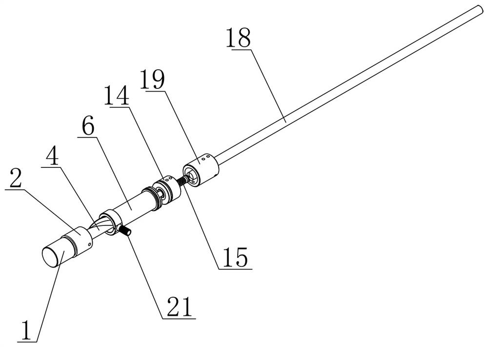
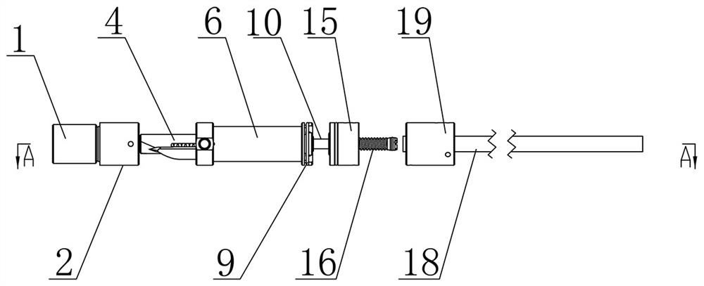
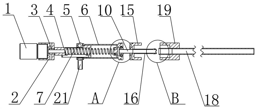
[0038] Such as figure 1 and figure 2 As shown, a toy gun soft bullet continuous firing device of the present invention includes a driving mechanism, a rotating rod 4, a ball 5, an elastic mechanism, a bullet loading handle 21, a guide groove pipe 6, a pushing mechanism, a gun barrel 18 and a gun barrel fixing part 19.

[0039] The driving mechanism drives the rotating rod 4 to rotate in one direction counterclockwise or clockwise. One end of the rotating rod 4 is connected with the driving mechanism, and the other end is inserted into the guide groove pipe 6 . Such as Figure 6 As shown, the rotating rod 4 is provided with a spiral groove, and one end of the guide groove pipe 6 is provided with a circular groove connected with the spiral groove, and the upper spring handle 21 is fixed on the guide groove pipe 6 at a position opposite to the circular groove, and the ball 5 is placed in the circular groove. Inside, the ball 5 rolls in the spiral groove to drive the guide tub...

Embodiment 2

[0049] Such as Figure 10 As shown, a toy gun of the present invention includes: a toy gun soft bullet continuous firing device shown in Embodiment 1 and a shell 20 arranged outside the toy gun soft bullet continuous firing device.

[0050] Such as Figure 11 As shown, the shell 20 is correspondingly provided with a handle hole 22, an observation hole 23, a clip hole 24, and a joint hole 25. Ball 5 just can not fall out. The observation hole 23 is used to observe whether there is a soft bullet in the gun barrel 18, the clip hole 24 is used to install a matching clip, the joint hole 25 is used to install a matching scope, the observation hole 23, the clip hole 24 and the joint hole 25 They are all matching settings for toy guns, and those skilled in the art know how to match the auxiliary facilities for installing toy guns, and will not repeat them here.

[0051] In one embodiment, in order to prevent random movement between the cage 15 and the housing 20 , a third sealing r...


PUM


Abstract

The invention belongs to the technical field of toys, and discloses a toy gun soft bullet continuous launching device which comprises a driving mechanism, a rotating rod, a ball, an elastic mechanism, a bullet feeding handle, a guide groove pipe, a pushing mechanism, a gun barrel and a gun barrel fixing part. The driving mechanism drives the rotating rod to unidirectionally rotate anticlockwise or clockwise, the ball is placed in the circular groove, and the ball rolls in the spiral groove so as to drive the guide groove pipe to slide; the elastic mechanism is used for quickly popping out of the guide groove pipe and forming high-pressure air flow in the guide groove pipe when the ball moves to the tail end of the rotating rod; one end of the pushing mechanism is inserted into one end of the guide groove pipe, and the other end is located behind the gun barrel and used for conveying high-pressure airflow. And the gun barrel penetrates through the gun barrel fixing part. Through repeated stress of the elastic mechanism and the pushing mechanism, continuous launching of soft bullets is achieved.

Description

technical field [0001] The invention belongs to the technical field of toys, and relates to a continuous launching device for soft bullets of a toy gun and a toy soft bullet gun including the launching device. Background technique [0002] In order to ensure the safety of children, toy guns usually use soft bullets made of soft materials. Toy soft bullet guns are highly entertaining and are loved by the majority of toy lovers. At present, the soft bullet launching devices on the market solve the problem of continuous loading. For example, the patent 201620468303.0 discloses the automatic pushing mechanism of the toy soft bullet gun, which adopts the method of incomplete gear and rack cooperation to drive the push rod to slide forward, and the fan When the tooth part meshes with the rack, the push rod is driven to slide forward. After the fan tooth part is disengaged from the rack, the push rod returns to the initial position under the action of the return spring, and the pu...

Claims


Application Information

Patent Timeline
Patent Type & Authority Applications(China)
IPC IPC(8): F41B7/08
CPCF41B7/08
Inventor 闫伟帝
Owner 闫伟帝
Why Eureka
Try Eureka