
Electromagnetic relay

An electromagnetic relay and electromagnetic system technology, applied in the direction of electromagnetic relays, electromagnetic relay details, relays, etc., can solve problems such as downward deformation, easy skewing of coil winding heads, and reducing the distance between coil 2 and yoke iron 4, etc., to achieve improved Pressure resistance performance, compact structure, effect of increasing air gap and creepage distance

Pending Publication Date: 2022-03-08
XIAMEN HONGFA SIGNAL ELECTRONICS CO LTD
View PDF0 Cites 2 Cited by
  • Summary
  • Abstract
  • Description
  • Claims
  • Application Information

AI Technical Summary

Problems solved by technology

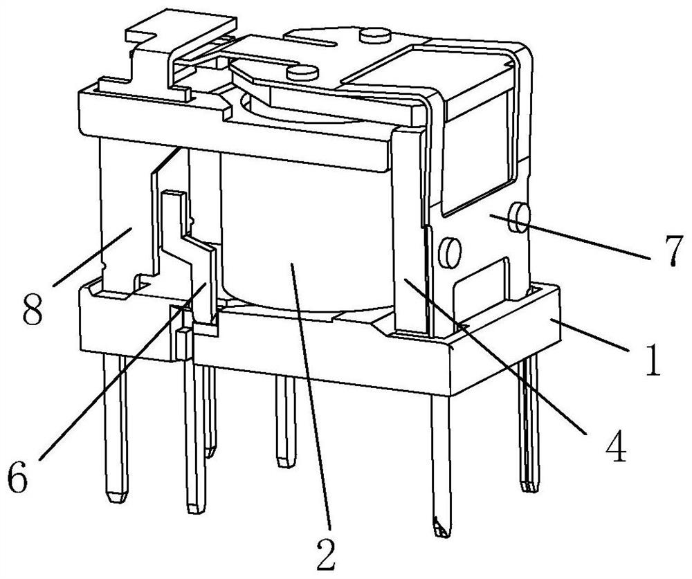
[0003] In this type of electromagnetic relay, there are currently the following defects: 1. As shown in Figure 3(b), the air gap L1 and the creepage distance L2 between the coil 2 and the yoke 4 are small, and the withstand voltage between the coil 2 and the contact The capacity is slightly greater than the critical value, and the pressure resistance margin is insufficient; 2. Since the yoke 4 is inserted from bottom to top during assembly, such as Figure 4 The base 1 is provided with an assembly hole 11', and the yoke 4 is inserted into the assembly hole 11' from bottom to top to complete the assembly; after the assembly, there is a certain gap between the yoke 4 and the base 1, so that there is glue penetration into internal phenomena, such as Figure 5 As shown, the normal glue penetrates to the range of the dotted line a
Once the glue has penetrated into the bending part of the movable spring (such as Image 6 In the area b shown), the reaction force of the relay is affected, and the product performance cannot be guaranteed
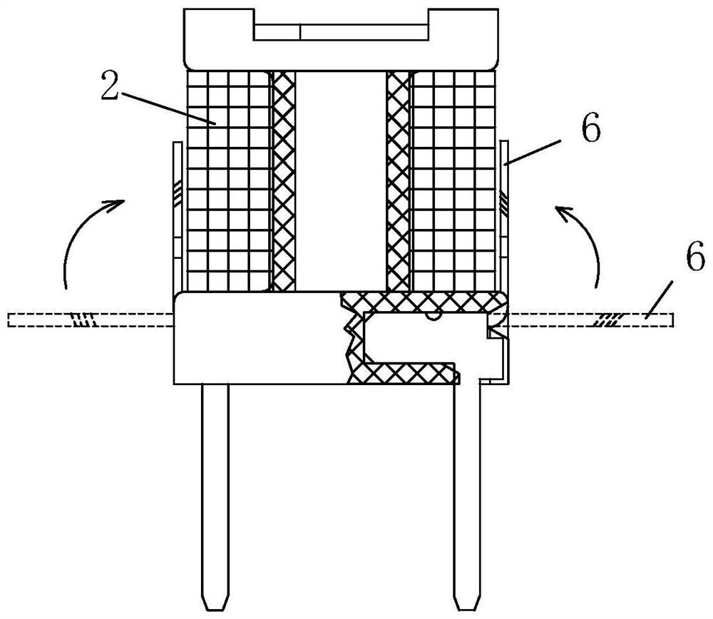
3. The space gap between the welding piece 6 and the static spring 8 is also unstable, as shown in Figure 3(a), after the coil winding is completed, the left and right welding pieces 6 have a straightening process, the welding piece in the figure The dotted line in 6 is the state before re-straightening, and the solid line is the state after re-straightening. During the re-straightening process, it is easy to cause the last coil of the coil 2 to loosen, thereby further reducing the distance between the coil 2 and the yoke 4, and during the assembly process Among them, the coil wrapping head of the welding piece 6 is easily skewed during the straightening process, as shown in Figure 3(b), when it is skewed toward the static spring 8, the air gap L3 between the coil wrapping head and the static spring 8 decreases, The withstand voltage between the coil contacts is close to the critical value, which is prone to insufficient withstand voltage
4. The static spring insertion part 12' on the base 1 is far away from the winding shaft 13', resulting in weak strength of the static spring insertion part 12', which is easily deformed downward due to the influence of the insertion force during the insertion process, resulting in The position of the static spring 8 moves down, that is, the position of the contact point moves down, which in turn causes the position of the moving contact of the moving spring 7 to be pressed down. The overall pressing angle of the moving spring 7 becomes larger, and the reaction force increases. The suction and reaction force matching characteristics of the product Affected, it may cause the action voltage of the product to increase, and there may even be a risk of non-action

Method used


Image

  • Electromagnetic relay
  • Electromagnetic relay
  • Electromagnetic relay

Examples


Embodiment Construction

[0053] To further illustrate the various embodiments, the present invention is provided with accompanying drawings. These drawings are a part of the disclosure of the present invention, which are mainly used to illustrate the embodiments, and can be combined with related descriptions in the specification to explain the operating principles of the embodiments. With reference to these contents, those skilled in the art should understand other possible implementations and advantages of the present invention. Components in the figures are not drawn to scale, and similar component symbols are generally used to denote similar components.

[0054] The present invention will be further described in conjunction with the accompanying drawings and specific embodiments.

[0055] refer to Figure 7 to Figure 22 As shown, an electromagnetic relay provided in this embodiment includes a base, an electromagnetic system and a contact system assembled on the base, the electromagnetic system in...


PUM


Abstract

The invention provides an electromagnetic relay which comprises a base, an electromagnetic system and a contact system, the electromagnetic system and the contact system are assembled on the base, and the electromagnetic system comprises a coil and a yoke; the base comprises a base and a coil frame, the coil frame comprises an upper flange, a lower flange and a winding shaft located between the upper flange and the lower flange, the coil is assembled on the winding shaft, the lower flange of the coil frame is connected with the base, the yoke is assembled on the base, the base is further integrally provided with an insulating wall in a protruding mode, and the insulating wall is connected with the coil frame. And the insulating wall is positioned between the coil and the yoke. Through simple design, the insulating medium is added between the coil and the yoke, so that the air gap and the creepage distance between the coil and the yoke can be effectively increased, and the voltage resistance is improved; and the structure is compact.

Description

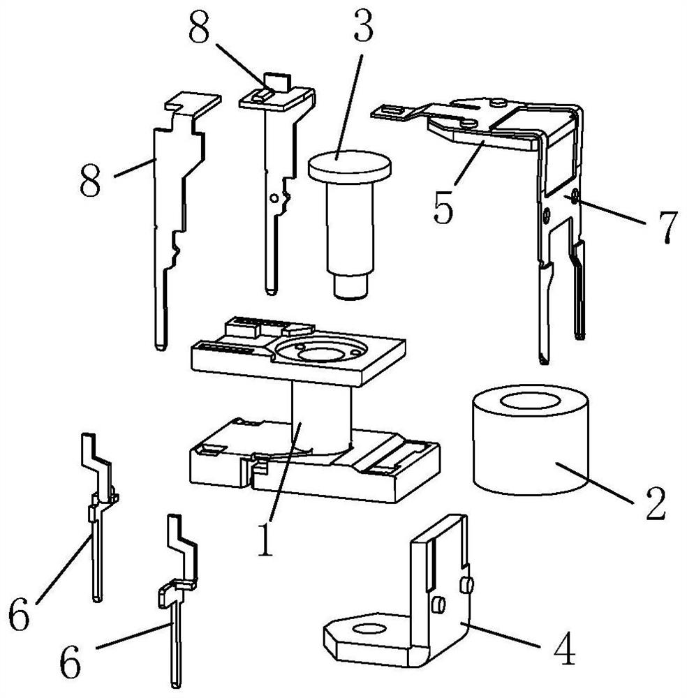
technical field [0001] The invention relates to the field of relays, in particular to an electromagnetic relay. Background technique [0002] Electromagnetic relay is an electronic control device; such as Figure 1 to Figure 6 Shown is a traditional electromagnetic relay, specifically a high-sensitivity relay, including a base 1 and an electromagnetic system and a contact system assembled on the base. The electromagnetic system includes a coil 2, an iron core 3, an armature 5 and a yoke 4. The contact system includes a moving spring 7 and a static spring 8 . The connection relationship and action principle of each component in the electromagnetic system and the contact system are all prior art, and will not be described in detail here. [0003] In this type of electromagnetic relay, there are currently the following defects: 1. As shown in Figure 3(b), the air gap L1 and the creepage distance L2 between the coil 2 and the yoke 4 are small, and the withstand voltage between ...

Claims


Application Information

Patent Timeline
Patent Type & Authority Applications(China)
IPC IPC(8): H01H50/02H01H50/04H01H50/14H01H50/36H01H50/44
CPCH01H50/026H01H50/04H01H50/44H01H50/36H01H50/041H01H50/14
Inventor 张宁毛启明董欣赏汪振华曹利超
Owner XIAMEN HONGFA SIGNAL ELECTRONICS CO LTD
Learn More