Connector fixing structure and fan fixing frame

A technology for fixing structures and connectors, which is applied in connection, installation of support structures, and installation of connecting parts, etc. It can solve problems such as hook breakage, plastic hook fatigue damage, and difficult disassembly of fixed structures.

Pending Publication Date: 2022-03-08
INVENTEC PUDONG TECH CORPOARTION +1
View PDF0 Cites 0 Cited by
  • Summary
  • Abstract
  • Description
  • Claims
  • Application Information

AI Technical Summary

Problems solved by technology

This fixed structure is not easy to disassemble and assemble, and the plastic hook is easy to be pulled or scratched by the metal frame during disass

Method used


Image

  • Connector fixing structure and fan fixing frame
  • Connector fixing structure and fan fixing frame
  • Connector fixing structure and fan fixing frame

Examples


Embodiment Construction

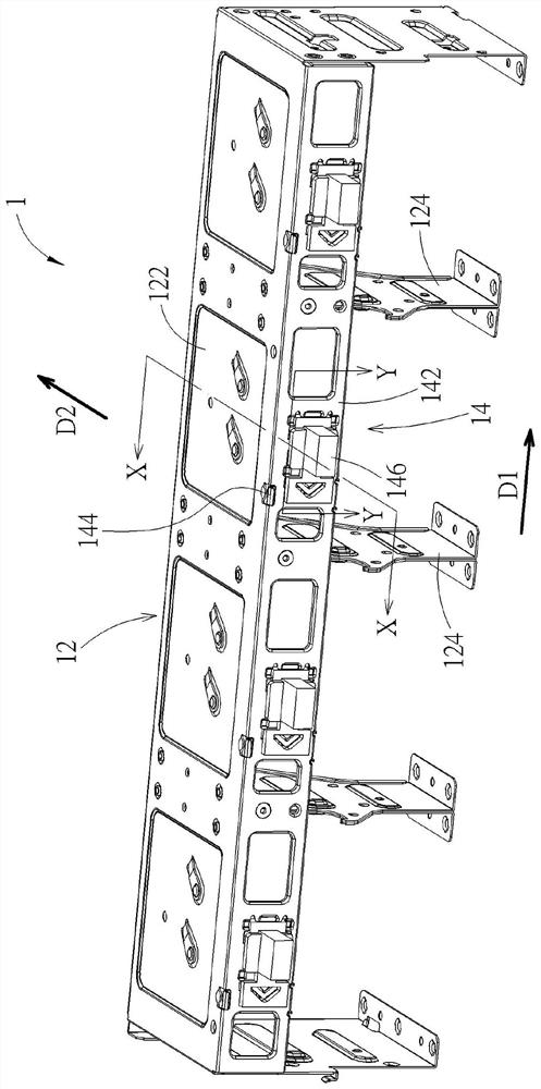
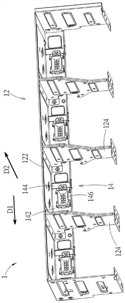
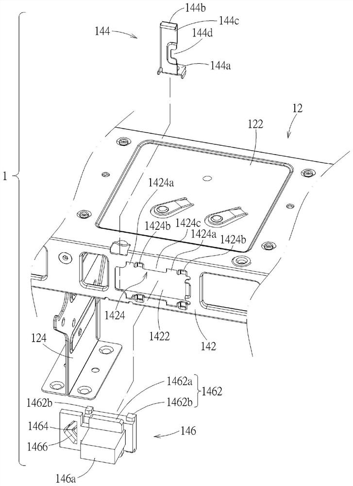
[0045] see Figure 1 to Figure 5 . A fan fixing frame 1 according to an embodiment includes a frame body 12 and a connector fixing structure 14 . The frame body 12 has a fan installation space 12 a formed between a top wall 122 and two side walls 124 . The connector fixing structure 14 includes a structural wall 142 , an elastic limiting member 144 and a connector body 146 . The structural wall 142 has a mounting hole 1422 and a first sliding engaging structure 1424 located on the edge of the mounting hole 1422 . The elastic limiting member 144 is disposed on the structural wall 142 adjacent to the installation hole 1422 . Connector body 146 (in Figure 5 It is shown as a single entity to simplify the drawing) with a second sliding engagement structure 1462 and a limiting portion 1464 . The connector body 146 slides and engages with the first sliding engagement structure 1424 in a sliding direction D1 (indicated by an arrow in the figure) to a predetermined position throu...


PUM


Abstract

The invention discloses a connector fixing structure and a fan fixing frame. The connector fixing structure comprises a structural wall, an elastic limiting piece and a connector body. The structure wall is provided with an installation hole and a sliding connection structure located on the edge of the installation hole. The elastic limiting piece is arranged on the structural wall close to the mounting hole. The connector body is provided with another sliding connection structure and a limiting part. The two sliding connection structures are connected in a sliding mode so that the connector body can be arranged at a preset position, the elastic limiting piece can restrain the limiting part, and the connector body can be fixed to the installation hole. Afterwards, the elastic limiting piece can be operated so that the elastic limiting piece can be separated from the limiting part, and the connector body is allowed to slide away from the preset position. A fan fixing frame forms a fan installation space and comprises the connector fixing structure. The connector body is exposed out of the fan installation space.

Description

technical field [0001] The invention relates to a connector fixing structure, in particular to a detachable connector fixing structure and a fan fixing frame with the detachable connector fixing structure. Background technique [0002] Some electronic devices, such as servers, have cooling systems that use fans to generate air flow. The power of the fan may be provided by the power module of the electronic device. The electronic device usually provides a fan fixing frame made of metal, on which a power connector is provided for plugging in a power cable of the fan. The power connector usually buckles the metal frame through a plastic hook to fix it on the fan fixing frame. This fixed structure is not easy to disassemble, and the plastic hook is easy to be pulled, scratched, etc. by the metal frame during disassembly, and even cause the hook to break. In addition, frequent disassembly and assembly will also cause fatigue damage to the hooks made of plastic. Contents of t...

Claims


Application Information

Patent Timeline
IPC IPC(8): H01R13/74H05K7/14H05K7/20
CPCH01R13/745H05K7/20718H05K7/20172H05K7/1485
Inventor 林德正吴俊龙
Owner INVENTEC PUDONG TECH CORPOARTION
Why Eureka
Try Eureka