

Electrode and battery using it
An electrode and battery technology, applied in the field of electrodes, can solve problems such as battery capacity reduction
- Summary
- Abstract
- Description
- Claims
- Application Information
AI Technical Summary
Problems solved by technology
Method used
Image

Examples
Embodiment 1-1 and 1-2
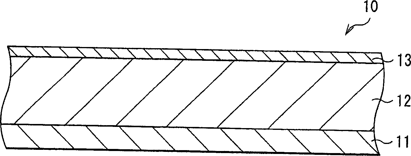
[0075] First, a 4 μm thick active material layer 12 made of silicon was formed on a current collector 11 made of a 20 μm thick copper foil by electron beam evaporation. Next, a 200 μm-thick thin film layer 13 made of nickel or copper was formed on the active material layer 12 by electron beam evaporation. Electrodes 10 of Examples 1-1 and 1-2 were thus formed. The thicknesses of the active material layer 12 and the thin film layer 13 were examined by SEM (scanning electron microscope).
[0076] Next step, utilize the electrode 10 that embodiment 1-1 and 1-2 form, make Figure 4 A coin-type secondary battery with a diameter of 20 mm and a thickness of 16 mm is shown. In the weight ratio of lithium cobaltate: carbon black: polyvinylidene fluoride = 92:3:5, active material lithium cobaltate (LiCoO 2 ) powder, conductive substance carbon black and binder polyvinylidene fluoride; the mixture is poured into the liquid carrier N-methylpyrrolidone to make a mixture slurry; the mixt...
Embodiment 2-1 to 2-4
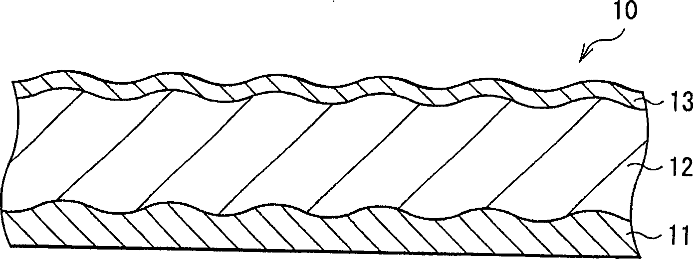
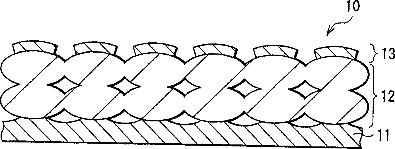
[0082]The electrode 10 is manufactured by forming the active material layer 12 by a sintering method. Specifically, first, a 20 μm thick copper foil or titanium foil is prepared as the current collector 11 . Then, a mixture slurry was prepared by adding N-methylpyrrolidone to a mixture obtained by mixing silicon powder having an average particle diameter of 1 μm and polyvinylidene fluoride at a weight ratio of 9:1. The mixture slurry is coated on the current collector 11 and heated to volatilize N-methylpyrrolidone. Next, the product was pressurized, and heat-treated and sintered at 300° C. for 8 hours in an argon atmosphere to form active material layer 12 . After forming the active material layer 12, on the surface of the active material layer 12, a 200 μm thick film layer 13 made of copper or a 200 μm thick film layer 13 made of nickel was formed by electron beam evaporation. Thus, the electrode 10 was produced. The thickness of the thin film layer 13 was examined by SEM...
Embodiment 3-1 to 3-6
[0089] As Examples 3-1 to 3-6 and Comparative Example 3, electrodes 10 were formed in a similar manner to Example 1-1 except that the active material layer 12 made of germanium was formed by electron beam evaporation to a thickness of 4 μm, And the thickness of the film layer 13 was changed as shown in Table 3. The thicknesses of the active material layer 12 and the thin film layer 13 were examined by SEM.
[0090] Then, by using the electrodes manufactured in Examples 3-1 to 3-6 and Comparative Example 3, Figure 5 and 6 secondary battery shown. Electrode 70 is formed like electrode 40 . The electrolyte layer 90 is formed by coating the precursor solution on the electrode 10 and the electrode 70 respectively, keeping the product at room temperature for 8 hours, and volatilizing dimethyl carbonate, wherein the precursor solution is mixed with 10 wt% of Block copolymer polyvinylidene fluoride and 60wt% dimethyl carbonate, and dissolve it in 30wt% of 42.5wt% ethylene carbona...
PUM
| Property | Measurement | Unit |
|---|---|---|
| thickness | aaaaa | aaaaa |
| thickness | aaaaa | aaaaa |
| diameter | aaaaa | aaaaa |
Abstract
Description
Claims
Application Information