
Window pulley rubber ring equidistant cutting equipment

An isometric cutting, rubber ring technology, applied in metal processing and other directions, can solve the problems of different lengths of rubber rings, high cutting cost, low accuracy, etc., to achieve consistent cutting length, increase cutting accuracy, and prevent rubber rings. deformation effect

Pending Publication Date: 2022-03-11
江西金百成五金制品有限公司
View PDF0 Cites 0 Cited by
  • Summary
  • Abstract
  • Description
  • Claims
  • Application Information

AI Technical Summary

Problems solved by technology

[0004] In order to overcome that the existing rubber ring cutting equipment needs to manually push the rubber ring when cutting the rubber ring, it is difficult to control the distance of the rubber ring manually, so that the length of the rubber ring is different, the accuracy is low, and it needs to consume More manpower, disadvantages of high cutting cost, technical problem: provide a window pulley that can push the rubber ring at equal distances, keep the cutting length of the rubber ring consistent, increase cutting accuracy, reduce manual operations, and reduce cutting costs Rubber ring isometric cutting equipment

Method used


Image

  • Window pulley rubber ring equidistant cutting equipment
  • Window pulley rubber ring equidistant cutting equipment
  • Window pulley rubber ring equidistant cutting equipment

Examples


Embodiment 1

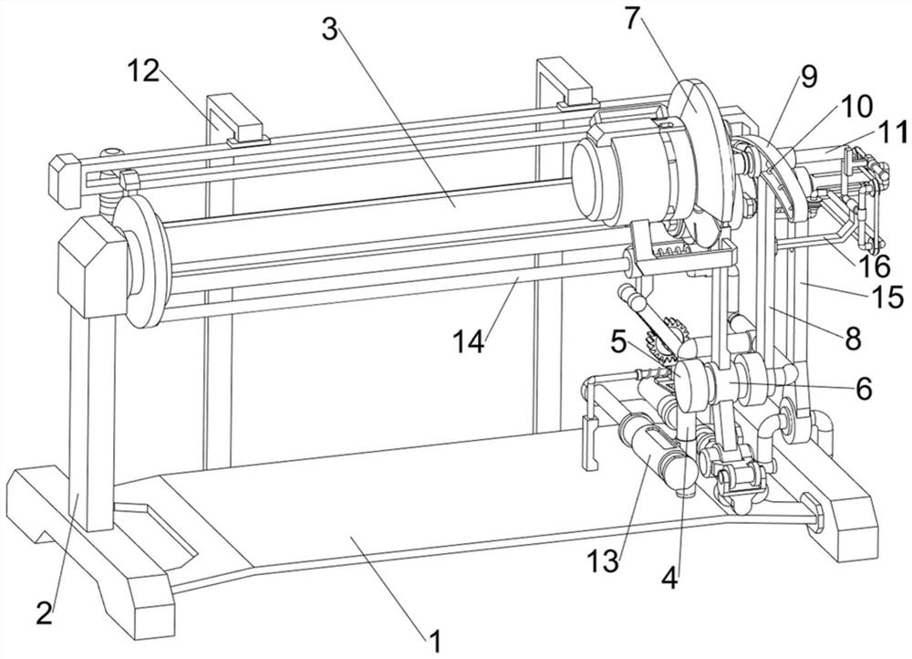
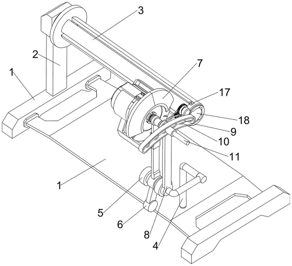
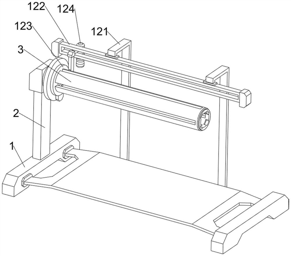
[0107] A window pulley rubber ring isometric cutting equipment such as Figure 1-6 As shown, it includes a base 1, an installation block 2, an upper barrel 3, a first support frame 4, a fixed block 5, a rotating plate 6, a cutting machine 7, a first support plate 8, a first guide frame 9, and a first spring 10. The first sliding block 11, the pushing mechanism 12 and the transmission mechanism 13, the left side of the top of the base 1 is provided with a mounting block 2, the upper right side of the mounting block 2 is rotatably provided with an upper cylinder 3, and the right side of the top of the base 1 is provided with The first bracing frame 4, the front left side of the first bracing frame 4 is provided with fixed block 5, and the rotation type in the middle part of fixed block 5 is provided with rotating plate 6, and cutting machine 7 is installed on rotating plate 6 tops, and cutting machine 7 internal rotary type is connected with For the rotating part, the front side...

Embodiment 2

[0114] On the basis of Example 1, such as figure 1 , Figure 7 , Figure 8 , Figure 9 , Figure 10 , Figure 11 , Figure 12 , Figure 13 , Figure 14 and Figure 15 As shown, a feed mechanism 14 is also included, and the feed mechanism 14 includes a first slide bar 141, a first connecting frame 142, a first fixed frame 143, a third spring 144, a fixed rod 145, a push block 146, a rotating frame 147, The first gear 148, the rack 149, the first guide rod 1410, the triangular block 1411, the top block 1412 and the back-moving spring 1413, the bottom right side of the push plate 123 is provided with the first slide bar 141, and the top of the first support frame 4 rear side is provided with There is a first connecting frame 142, the top of the first connecting frame 142 is provided with a first fixing frame 143, the first fixing frame 143 is slidingly matched with the first sliding rod 141, the material outside the first sliding rod 141 is a damping material, and the fir...


PUM


Abstract

The invention relates to cutting equipment, in particular to equidistant cutting equipment for window pulley rubber rings. According to the equidistant cutting equipment for the window pulley rubber rings, the rubber rings can be pushed equidistantly, the cutting lengths of the rubber rings are kept consistent, the cutting accuracy is increased, manual operation is reduced, and the cutting cost is reduced. A window pulley rubber ring equidistant cutting device comprises a base, and a mounting block is arranged on one side of the top of the base. The device has the beneficial effects that a first connecting block drives a sleeve rod to move forwards, the sleeve rod drives a sliding block to move forwards, then the sliding block extrudes a first spring, the first spring is slightly compressed, the first spring drives a second connecting block to move forwards, and the second connecting block drives a rotating frame to rotate in the process of moving forwards; and the rotating frame drives the rotating plate and the cutting machine to rotate towards the rear side, and then the cutting machine can cut the rubber ring, so that the rubber ring can be cut at equal intervals.

Description

technical field [0001] The invention relates to a cutting device, in particular to an equidistant cutting device for a rubber ring of a window pulley. Background technique [0002] At present, in the process of processing and producing pulleys, manufacturers generally process a layer of rubber ring on the outer ring of the pulley. The rubber ring can assist the pulley to reduce noise during the movement process, and at the same time can assist the pulley to move better, thus facilitating It is necessary to cut the rubber ring so that the rubber ring can be cut into a size that can match the pulley. At present, the rubber ring is generally cut by using the rubber ring cutting equipment to cut the rubber ring. The existing rubber ring cutting equipment is on the When cutting the rubber ring, it is necessary to manually push the rubber ring, and then cut the rubber ring through the cutting equipment, and push the rubber ring manually, it is difficult to control the distance of ...

Claims


Application Information

Patent Timeline
Patent Type & Authority Applications(China)
IPC IPC(8): B26D1/18B26D5/08B26D7/01B26D7/06
CPCB26D1/18B26D5/083B26D7/01B26D7/06B26D2007/013
Inventor 曾微罗仁波
Owner 江西金百成五金制品有限公司
Learn More