Shearing device for automatically distinguishing positions of capacitor pins of electronic components

A technology for electronic components and cutting devices, applied in the field of electronic components, can solve the problems of too short pin cutting, economic loss, unfavorable use, etc., and achieve consistent cutting length, high degree of automation, and automatic replacement. bit effect

Inactive Publication Date: 2021-11-30
上海榆珩机电装备有限公司
View PDF0 Cites 0 Cited by
  • Summary
  • Abstract
  • Description
  • Claims
  • Application Information

AI Technical Summary

Problems solved by technology

At present, when cutting the feet, the staff usually cut them manually. There is a certain error in the cutting position, and it is easy to cut the pins too short, which will affect the use.
However, the existing automatic cutting device requires the staff to manually place the two pins of the capacitor at the cutting place, but the processing volume is too large, and there is work negligence, so that when the capacitor is placed, the long pins and the short pins are separated. The wrong placement position causes excessive cutting of long pins and invalid cutting of short pins, which is not only not conducive to use, but also affects the staff's ability to distinguish the positive and negative poles of the capacitor, resulting in unqualified capacitor cutting, resulting in unnecessary Economic losses

Method used


Image

  • Shearing device for automatically distinguishing positions of capacitor pins of electronic components
  • Shearing device for automatically distinguishing positions of capacitor pins of electronic components
  • Shearing device for automatically distinguishing positions of capacitor pins of electronic components

Examples


Embodiment 1

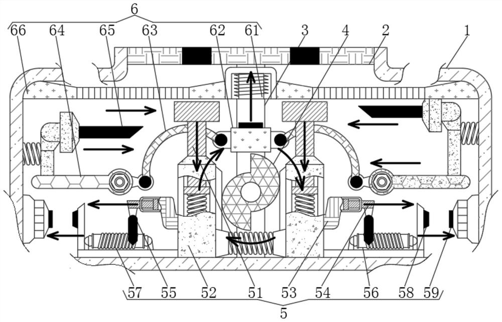
[0022] see Figure 1-3 , a shearing device for automatically identifying the position of capacitor pins of electronic components, including a housing 1, a placement table 2, a support rod 3, a rotary block 4, a driving mechanism 5 and a shearing mechanism 6.

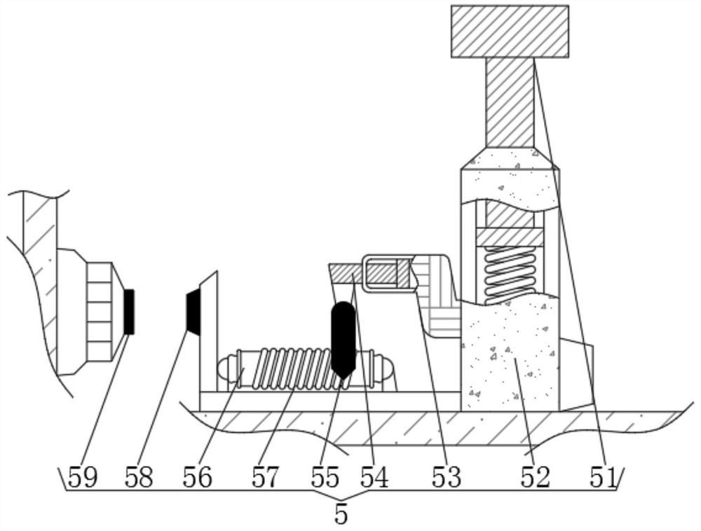
[0023] The drive mechanism 5 includes a pressure rod 51, the outer side of the pressure rod 51 is sleeved with an outer tube 52, the outer side of the outer tube 52 is welded with a side tube 53, the inside of the side tube 53 is movably connected with a piston 54, and the bottom of the piston 54 is welded with a Metal sliding piece 55, the rear side of metal sliding piece 55 is provided with insulating tube 56, and the outer side of insulating tube 56 is wound with resistance coil 57, and the outer side of insulating tube 56 is provided with extruding rod 58, and extruding rod 58 is far away from insulating tube 56 One side of is provided with button 59.

[0024] There are two pressure rods 51 with the same specificati...

Embodiment 2

[0027] see Figure 1-3 , a shearing device for automatically identifying the position of capacitor pins of electronic components, including a housing 1, a placement table 2, a support rod 3, a rotary block 4, a driving mechanism 5 and a shearing mechanism 6.

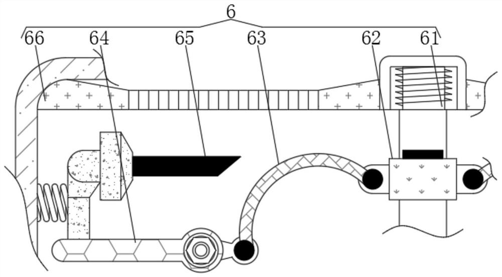
[0028] Also includes a shearing mechanism 6, the shearing mechanism 6 includes an electromagnet 61, a cover block 62 is slidably connected to the bottom of the electromagnet 61, and both sides of the cover block 62 are rotatably connected with a rotating rod 63, and the rotating rod 63 is away from the sleeve block One side of 62 is slidably connected with moving bar 64, and the top of moving bar 64 is provided with cutter 65, and the both sides of electromagnet 61 are connected with connecting frame 66, and electromagnet 61 is electrically connected with left side resistance coil 57, simultaneously It is electrically connected with the button 59, and the inside of the cover block 62 is provided with a through hole, and ...

Embodiment 3

[0031] see Figure 1-3 , a shearing device for automatically identifying the position of capacitor pins of electronic components, including a housing 1, a placement table 2, a support rod 3, a rotary block 4, a driving mechanism 5 and a shearing mechanism 6.

[0032] The drive mechanism 5 includes a pressure rod 51, the outer side of the pressure rod 51 is sleeved with an outer tube 52, the outer side of the outer tube 52 is welded with a side tube 53, the inside of the side tube 53 is movably connected with a piston 54, and the bottom of the piston 54 is welded with a Metal sliding piece 55, the rear side of metal sliding piece 55 is provided with insulating tube 56, and the outer side of insulating tube 56 is wound with resistance coil 57, and the outer side of insulating tube 56 is provided with extruding rod 58, and extruding rod 58 is far away from insulating tube 56 One side is provided with button 59.

[0033] There are two pressure rods 51 with the same specifications...


PUM


Abstract

The invention relates to the technical field of electronic components, and discloses a shearing device for automatically distinguishing the positions of capacitor pins of electronic components. The shearing device comprises a driving mechanism, the driving mechanism comprises pressed rods. The pins of the capacitors extrude the two pressed rods, the pressed rods move downwards to cause pistons to move, metal slip sheets synchronously move on the surfaces of resistance coils, the shearing operation and the transposition operation are controlled according to the difference between the placing state of the capacitors and the length of the pins, shearing is automatically carried out on the pins, compared with a common manual shearing mode, the shearing length is kept consistent, the shearing effect is better, a rotating block rotates to push two side pipes to be far away from each other, the pressed rods move synchronously, so that the transposition operation of the capacitors is not influenced, the placement positions of the two pins are not changed, automatic transposition of the pins is realized, shearing is carried out on the pins subjected to transposition, and therefore unnecessary loss caused by wrong pin shearing due to errors of workers is effectively avoided, the pin shearing success rate is increased, the operation is convenient, and the practicability is higher.

Description

technical field [0001] The invention relates to the technical field of electronic components, in particular to a cutting device for automatic position identification of capacitance pins of electronic components. Background technique [0002] Capacitors are indispensable electronic components in the fields of electronics and electric power. Mainly used in power supply filtering, signal filtering, signal coupling, resonance, filtering, compensation, charging and discharging, energy storage, DC blocking and other circuits. During the production and processing of capacitors, because the length of the pins does not meet the actual use requirements, the pins on the surface protrude on the circuit board, and it is necessary to cut the pins. At present, when cutting the pins, the staff usually cut them manually. There is a certain error in the cutting position, and it is easy to cut the pins too short, which will affect the use. However, the existing automatic cutting device requi...

Claims


Application Information

Patent Timeline
Patent Type & Authority Applications(China)
IPC IPC(8): B21F11/00
Inventor 周印通
Owner 上海榆珩机电装备有限公司
Why Eureka
Try Eureka