90-degree power valve capable of automatically dredging

An automatic and dynamic technology, applied in the direction of valve lifter, valve device, engine components, etc., can solve the problems of silted powder, unable to solve the problem of powder penetration and deposition, and increase the friction of the gap.

Pending Publication Date: 2022-03-11
FOSHAN HUMAN HABITAT ENVIRONMENTAL PROTECTION ENG +1
View PDF0 Cites 0 Cited by
  • Summary
  • Abstract
  • Description
  • Claims
  • Application Information

AI Technical Summary

Problems solved by technology

[0002] The valves of the existing pneumatic ash conveying system usually adopt dynamic gate valves, dynamic ball valves or dynamic flap valves. After the dynamic gate valves are used for a period of time, on the one hand, some ultra-fine powders will enter the tight fit gap between the gate knife and the valve body. Increase the friction of the gap, and finally the gap will expand, resulting in the failure of the tight fit and airtightness; Cleaning, therefore, continuous silting, compaction, and elevation will eventually lead to the groove being filled and leveled, and the knife cannot be inserted into the groove, resulting in the airtightness of the knife and the groove
After the power ball valve is used for a period of time, some ultra-fine powder will enter the tight fit gap between the ball valve and the valve body, increasing the resistance value, causing the ball valve to fail to close and open normally
For the power flap valve, in order to be able to be sealed with the pipeline, the outermost layer of the flap valve is usually made of elastic plastic or rubber sleeves, and the plastic or rubber sleeves become the face-to-face contact with the powder when the power flap valve is open. The collision situation is easily destroyed by dust friction, so it cannot be airtight
There are problems that cannot solve the problem of powder penetration and deposition

Method used


Image

  • 90-degree power valve capable of automatically dredging
  • 90-degree power valve capable of automatically dredging
  • 90-degree power valve capable of automatically dredging

Examples


Embodiment Construction

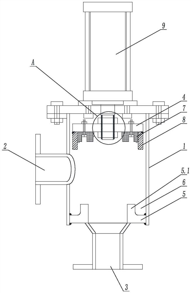
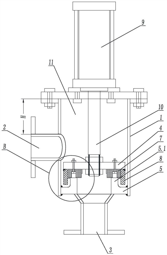
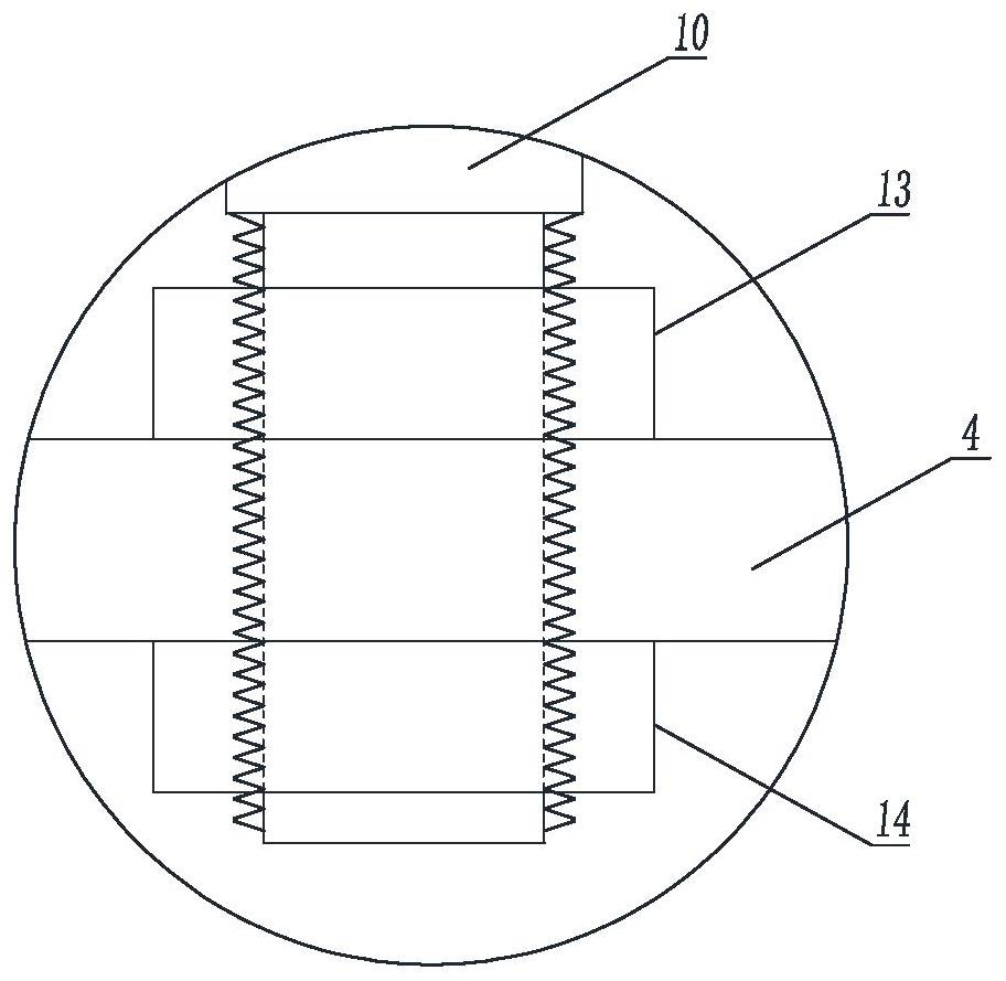
[0021] figure 1 It is a structural schematic diagram of the present invention; figure 2 Schematic diagram of the structure of the valve closed; image 3 for figure 1 Enlarged view of Part A of ; Figure 4 for figure 2 Enlarged view of Part B of ; Figure 5 It is a schematic diagram of the structure that the valve is about to close; Figure 6 Side view of the self-dredging annular toothed ring. Such as Figures 1 to 6 As shown, a 90-degree power valve for automatic desilting includes a valve body 1, the top of the valve body 1 is sealed by an upper cover plate, the inlet port 2 is set on one side of the valve body 1, and the outlet port 3 is set on the valve body 1 The bottom end, the inlet end 2 and the outlet end 3 are at 90 degrees, and also include a lower pressure plate 4 and an annular bottom plate 5, the lower pressure plate 4 and the annular bottom plate 5 are arranged in the valve body 1, and the annular bottom plate 5 is arranged at the bottom of the valve bo...


PUM


Abstract

The invention belongs to the field of pneumatic ash conveying system valves, and particularly relates to an automatic dredging 90-degree power valve which comprises a valve body, a lower pressing plate and an annular bottom plate, the top of the valve body is sealed through an upper cover plate, an inlet end is arranged on one side of the valve body, an outlet end is arranged at the bottom end of the valve body, and the inlet end and the outlet end form a 90-degree angle. The lower pressing plate and the annular bottom plate are arranged in the valve body, the annular bottom plate is arranged at the bottom of the valve body and connected with the inner wall of the valve body in a welded mode, a U-shaped groove is formed by the annular bottom plate and the inner surface of the valve body, and a sealing gasket matched with the annular bottom plate is arranged on the lower end face of the lower pressing plate. An automatic dredging annular tooth-shaped ring matched with the U-shaped groove is arranged on the lower end face of the lower pressing plate, a through hole is formed in the middle of the lower pressing plate, a driving valve is arranged at the top end of the valve body and fixedly connected with the lower pressing plate through a nut, and a storage bin is arranged on the upper portion of the inner side of the valve body. According to the automatic dredging device, automatic dredging is achieved, the sealing gasket is effectively protected against dust abrasion, and the sealing gasket is durable.

Description

technical field [0001] The invention belongs to the field of pneumatic ash conveying system valves, in particular to a 90-degree power valve for automatic dredging. Background technique [0002] The valves of the existing pneumatic ash conveying system usually adopt dynamic gate valves, dynamic ball valves or dynamic flap valves. After the dynamic gate valves are used for a period of time, on the one hand, some ultra-fine powders will enter the tight fit gap between the gate knife and the valve body. Increase the friction of the gap, and finally the gap will expand, resulting in the failure of the tight fit and airtightness; Cleaning, therefore, continuous accumulation, compaction, and elevation eventually lead to the groove being filled and leveled, and the switch knife cannot be inserted into the groove, causing the switch knife and the groove to be unable to be airtight. After the power ball valve is used for a period of time, some ultra-fine powder will enter the tight ...

Claims


Application Information

Patent Timeline
Patent Type & Authority Applications(China)
IPC IPC(8): F16K1/36F16K1/46
CPCF16K1/36F16K1/46
Inventor 黄清豹黄霈淇
Owner FOSHAN HUMAN HABITAT ENVIRONMENTAL PROTECTION ENG
Why Eureka
Try Eureka