Water drainage and pressure reduction device for roads and bridges

A technology for drainage and decompression, used in bridges, applied in bridges, bridge construction, bridge parts, etc., can solve problems such as affecting water discharge, inability to centralize garbage disposal, blocking drainage devices, etc., to achieve the effect of convenient operation and improved practicability

Active Publication Date: 2022-06-07
SHANXI TRAFFIC PLANNING PROSPECTING & DESIGN INST
View PDF11 Cites 0 Cited by
  • Summary
  • Abstract
  • Description
  • Claims
  • Application Information

AI Technical Summary

Problems solved by technology

[0003] Traditional drainage and decompression devices generally belong to the drainage mechanism, which drains the accumulated water on the road to a lower position and then discharges it. However, this method has certain defects. When there is garbage accumulated on the road, the drainage device will be blocked. In turn, it will affect the discharge of water. At the same time, traditional devices cannot centrally treat garbage, and artificial collection is very cumbersome.

Method used


Image

  • Water drainage and pressure reduction device for roads and bridges
  • Water drainage and pressure reduction device for roads and bridges
  • Water drainage and pressure reduction device for roads and bridges

Examples


Embodiment 1

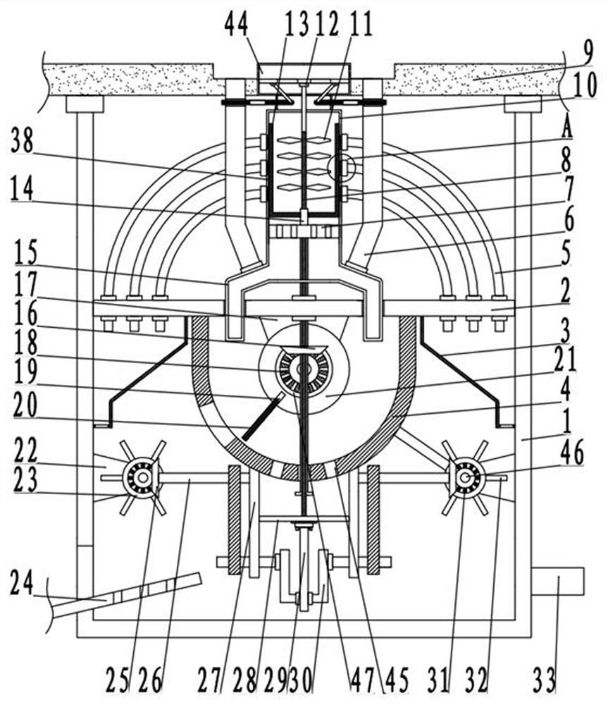
[0027] see Figure 1-5 , a drainage pressure reducing device for roads and bridges, comprising a pipeline 1, and also comprising:

[0028] A mounting plate 2 is fixedly arranged in the pipeline 1, a diversion cylinder 10 is arranged on the installation plate 2, a collecting bin 4 is fixedly arranged at the bottom of the mounting plate 2, a road body 9 is arranged on the top of the pipeline 1, and the diversion cylinder 10 is arranged. Fixed connection with the road body 9;

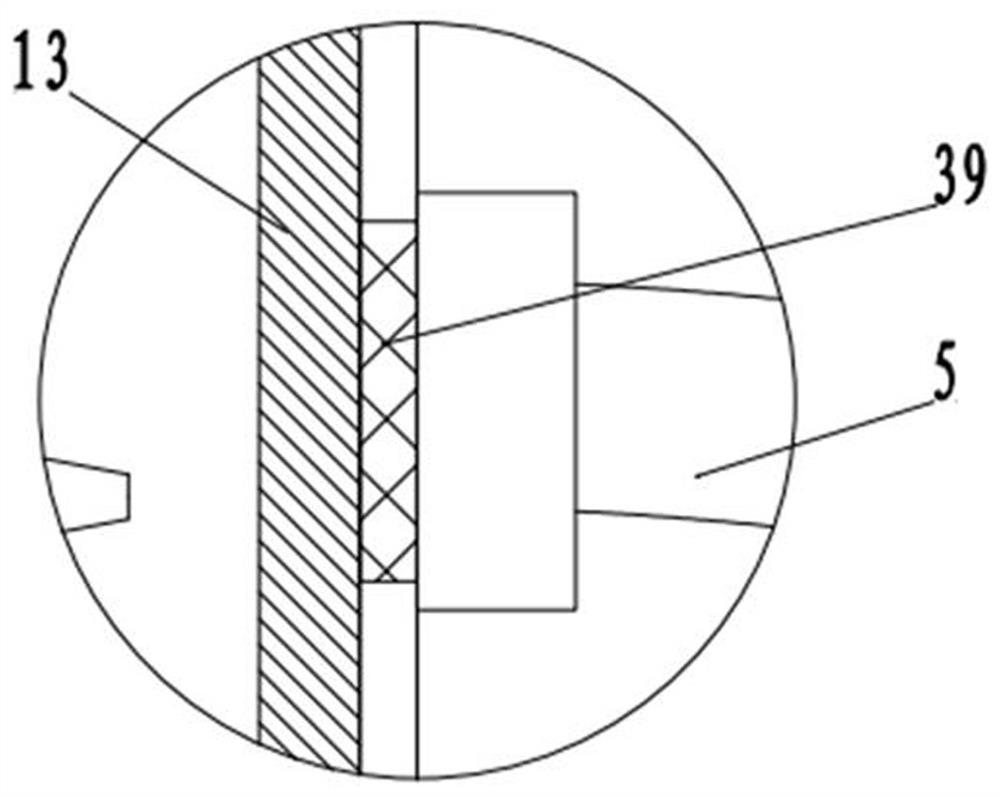
[0029] The drainage mechanism 12 provided on the diversion cylinder 10 includes a filter plate 7 fixedly arranged in the diversion cylinder 10. The filter plate 7 is provided with a crushing component 38, and a drainage component 44 is set above the diversion cylinder 10. The side walls on both sides of the flow cylinder 10 are fixedly connected to the shunt pipe 5, and the side wall of the guide cylinder 10 on one side of the shunt pipe 5 is fixedly provided with a filter screen 39. The shunt pipes 5 are...

Embodiment 2

[0033] see Figure 1-5, the other content of this embodiment is the same as that of Embodiment 1, the difference is that: the pulverizing assembly 38 includes a rotating drum 14 that is rotatably arranged on the filter plate 7, and a rotating column 8 is slid up and down in the rotating drum 14. The crushing knife 11 is fixedly connected to the rotating column 8 in the guide cylinder 10, and the top wall of the rotating cylinder 14 below the crushing knife 11 is fixedly connected to the scraper rod 13. The rotation of the rotating cylinder 14 can drive the rotating column 8 to rotate, and the rotating column 8 can It slides up and down relative to the rotating drum 14, thereby realizing the up-and-down movement and crushing, which makes the crushing more thorough, the crushing efficiency is higher, and the overall dredging of the pipeline 1 is more convenient.

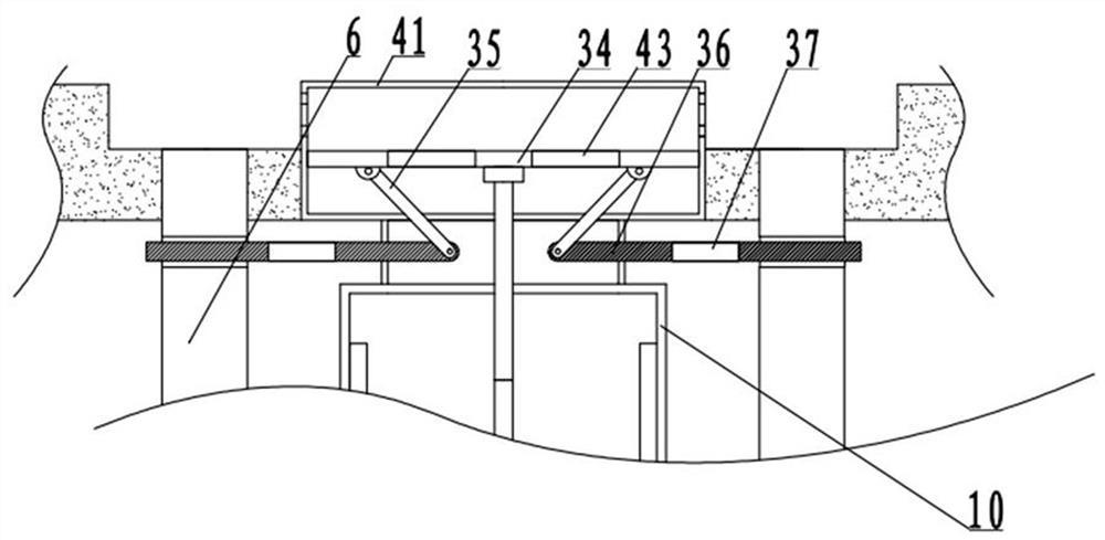
[0034] The launching assembly 44 includes a feeding head 41, the feeding head 41 is a metal mesh cylindrical structu...


PUM


Abstract

The invention discloses a drainage and pressure reduction device for roads and bridges, and relates to the technical field of road and bridge equipment, the drainage and pressure reduction device comprises a pipeline and further comprises a mounting plate fixedly arranged in the pipeline, a guide cylinder is arranged on the mounting plate, a collecting bin is fixedly arranged at the bottom of the mounting plate, a road body is arranged at the top of the pipeline, and the guide cylinder is fixedly connected with the road body; the drainage mechanism arranged on the guide cylinder comprises a filter plate fixedly arranged in the guide cylinder, a smashing assembly is arranged on the filter plate, a drainage assembly is arranged above the guide cylinder, and the side walls of the two sides of the guide cylinder are fixedly connected with flow dividing pipes. Therefore, auxiliary drainage and pressure reduction are realized, and the drainage performance of the device is improved; and a driving assembly is arranged below the material collecting bin, the driving assembly is impacted by external water flow to drive the transmission assembly, and the waste crushing device is used for crushing waste while discharging.

Description

technical field [0001] The invention relates to the technical field of road bridge equipment, in particular to a drainage pressure reducing device for road bridges. Background technique [0002] With the development of my country's transportation industry, roads and bridges, as special road structures that can cross terrain, have become a very important part of transportation development. People's driving on roads and bridges needs to be guaranteed to prevent the internal structure of bridges from being eroded by rainwater. To affect its service life, it is necessary to set up a perfect drainage system for roads and bridges to avoid rainwater accumulation and cause danger to passing vehicles. [0003] The traditional drainage and decompression device generally belongs to the drainage mechanism, which diverts the accumulated water on the road to a lower position and then discharges it. However, this method has certain defects. When there is accumulated garbage on the road, the...

Claims


Application Information

Patent Timeline
Patent Type & Authority Applications(China)
IPC IPC(8): E01D19/08
CPCE01D19/086Y02A20/108
Inventor 翟晓春王添荣毛莹莹段飞飞张晨铃徐金华蔡先强
Owner SHANXI TRAFFIC PLANNING PROSPECTING & DESIGN INST
Why Eureka
Try Eureka