Exhaust gas treatment catalyst automatic feeding and dredging system

A technology of automatic feeding and exhaust gas treatment, which is applied in the system field of catalyst honeycomb channel dredging, can solve the problems of high labor cost, high labor intensity, and low dredging efficiency, and achieve the effect of high degree of automation and high dredging efficiency

Active Publication Date: 2020-03-31
CHONGQING INST OF MECHANICAL & ELECTRICAL ENG
View PDF4 Cites 0 Cited by
  • Summary
  • Abstract
  • Description
  • Claims
  • Application Information

AI Technical Summary

Problems solved by technology

[0003] However, in the high-ash flue gas environment in my country, after long-term use, the pores of the honeycomb catalyst are easily blocked by the deposition of fly ash and sulfate, resulting in an increase in the pressure drop of the denitration reactor and a decrease in the denitrification efficiency. Frequent cleaning of the honeycomb pores is required. , effectively remove the clogged dirt in the catalyst pores
[0004] At present, the cleaning of the blockage in the catalyst channel is manually controlled by the dredging head to reciprocate up and down in the honeycomb channel and combined with flushing. The dredging efficiency is low, the labor cost is high, and the labor intensity is high.

Method used


Image

  • Exhaust gas treatment catalyst automatic feeding and dredging system
  • Exhaust gas treatment catalyst automatic feeding and dredging system
  • Exhaust gas treatment catalyst automatic feeding and dredging system

Examples


Embodiment Construction

[0029] Below by embodiment and in conjunction with accompanying drawing, the present invention will be further described:

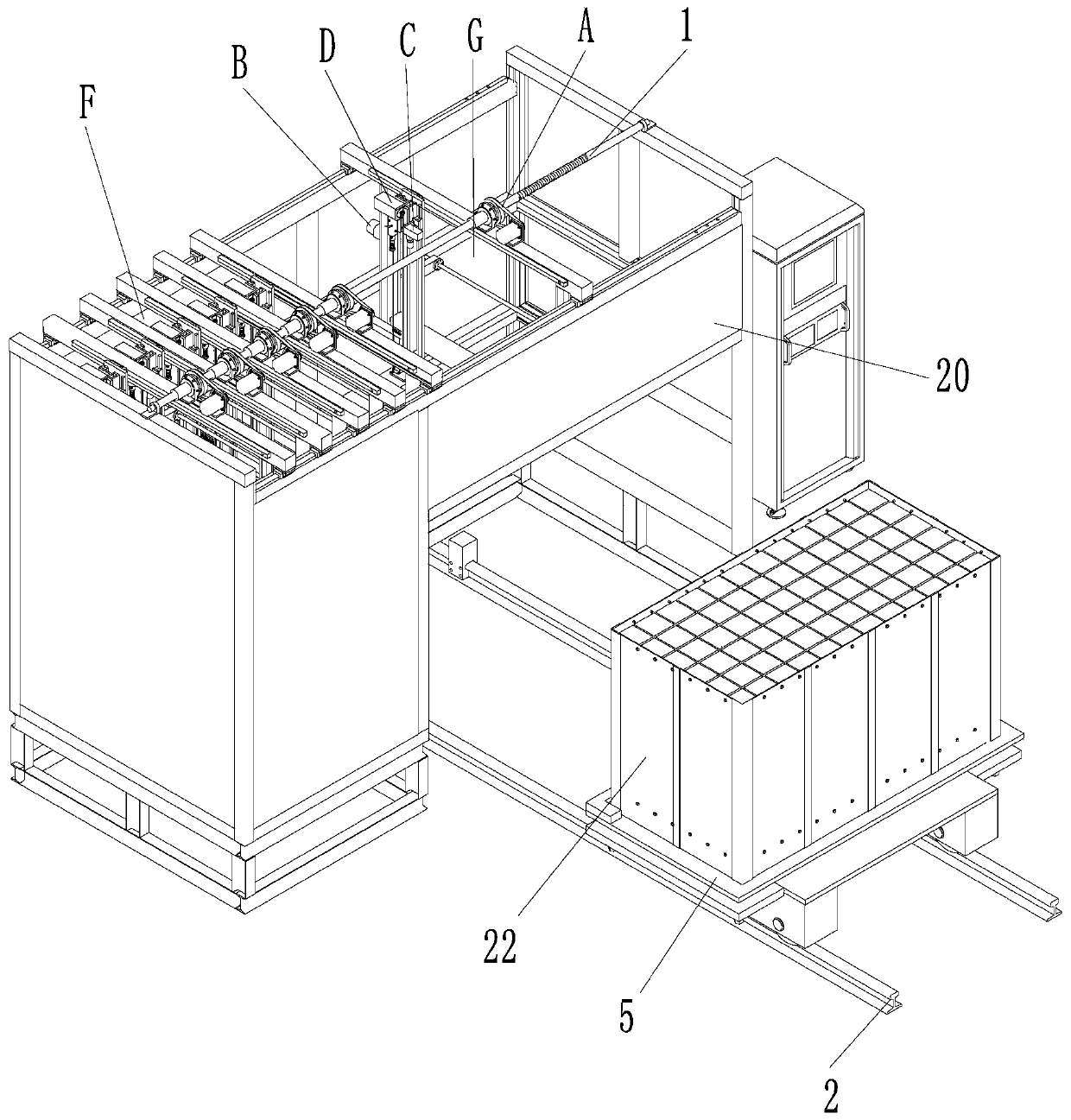
[0030] Such as figure 1 The exhaust gas treatment catalyst automatic feeding and dredging system shown is mainly composed of three parts: feeding track 2, feeding trolley 5, and catalyst dredging equipment. The feeding track 2 and the feeding trolley 5 are used for automatic feeding of workpieces, and the catalyst dredging equipment is used for automatic dredging of the honeycomb channels of workpieces.

[0031] combine figure 1 , Figure 8 , Figure 9 As shown, the feeding trolley 5 can move along the feeding track 2 under the drive of power to enter or exit the catalyst dredging equipment. The feeding track is divided into two tracks arranged side by side. Preferably, a limit block 17 and a photoelectric sensor (not shown in the figure) are arranged at the end of the feeding track 2 as positioning devices. The photoelectric sensor advances the lim...


PUM


Abstract

The invention relates to an automatic feeding and dredging system for waste gas treatment catalysts. A feeding trolley can move along a feeding track to enter or withdraw from a catalyst dredging device. The catalyst dredging device comprises a left-right travelling mechanism, front-back travelling mechanisms, lens lifting mechanisms and dredging head feeding mechanisms. The left-right travellingmechanism comprises a fixed lead screw and a plurality of first nuts. The first nuts sleeve the fixed lead screw in a left-right spaced mode. The front-back travelling mechanisms comprise rotating lead screws and second nuts sleeving the rotating lead screws. The rotating lead screws rotate under power drive, and drive a vertical mounting base to move forwardly and backwardly through the second nuts. Each lens lifting mechanism comprises a first gear and rack mechanism and a camera. Each dredging head feeding mechanism comprises a second gear and rack mechanism and a dredging component. The automatic feeding and dredging system has the advantages that through independent control of each front-back travelling mechanism, each dredging component and each camera are driven independently, so that blocked portions of honeycomb ducts can be positioned by camera shooting and then dredged automatically, and automatic feeding can be achieved.

Description

technical field [0001] The invention relates to the technical field of catalyst dredging, in particular to a system capable of realizing automatic catalyst feeding and then dredging catalyst honeycomb channels. Background technique [0002] With the increasingly stringent national environmental protection policies, the emission control standards of flue gas pollutants are also gradually increasing, and the use of catalysts to treat flue gas is considered to be an effective method to reduce nitrogen oxide emissions. For a long time, honeycomb catalyst has the highest market share in my country's catalyst market, so it is widely used in the treatment of flue gas pollutants in thermal power plants, glass factories and other industries. [0003] However, in the high-ash flue gas environment in my country, after long-term use, the pores of the honeycomb catalyst are easily blocked by the deposition of fly ash and sulfate, resulting in an increase in the pressure drop of the denit...

Claims


Application Information

Patent Timeline
Patent Type & Authority Patents(China)
IPC IPC(8): B01D53/88B01D53/56B01D53/96
CPCB01D53/8631B01D53/88B01D53/96B01D2258/0283
Inventor 何紫林管维柱谢小浩田波黄梅陈胡芳
Owner CHONGQING INST OF MECHANICAL & ELECTRICAL ENG
Why Eureka
Try Eureka