An automatic desilting clear water tank of a sandstone production wastewater treatment system and its use method

A technology for production wastewater and treatment system, applied in separation methods, chemical instruments and methods, precipitation separation, etc., can solve the problems of high labor intensity, reduce the operating rate of wastewater treatment system, and turbid production water, so as to reduce labor intensity and improve Start-up rate and production efficiency, avoid the effect of manual dredging

Active Publication Date: 2021-12-14
SINOHYDRO BUREAU 9
View PDF34 Cites 0 Cited by
  • Summary
  • Abstract
  • Description
  • Claims
  • Application Information

AI Technical Summary

Problems solved by technology

[0002] The traditional waste water treatment system of the gravel production line is the system recorded in the two-stage centrifugal desliming process disclosed in the Chinese patent No. 201110101333X applied by the unit; since the water treated by the vertical flow clarifier and the high-efficiency fast clarifier directly flows into the Clear water pool, and the clear water pool adopts a single-pipe water outlet method. The outlet pipe is located at a corner of the pool, and cannot pump water to the entire pool bottom at the same time, causing a large amount of suspended matter and fine particles in the water to settle at the bottom of the clear water pool. When there are too many particles, floating objects and fine particles will settle in 3 months to produce silt to block the water inlet of the pipeline pump, and at the same time cause the production water in the clean water tank to be turbid and reduce the water quality. At this time, the system can only be stopped and the clean water tank should be cleaned Manual desilting, it takes 2 to 3 days to desilt the clear water pool once, and the labor intensity is high, which reduces the start-up rate of the wastewater treatment system and reduces the production efficiency

Method used


Image

  • An automatic desilting clear water tank of a sandstone production wastewater treatment system and its use method
  • An automatic desilting clear water tank of a sandstone production wastewater treatment system and its use method
  • An automatic desilting clear water tank of a sandstone production wastewater treatment system and its use method

Examples


Embodiment Construction

[0015] The technical solution of the present invention is further described below, but the scope of protection is not limited to the description.

[0016] see Figure 1 to Figure 5 shown.

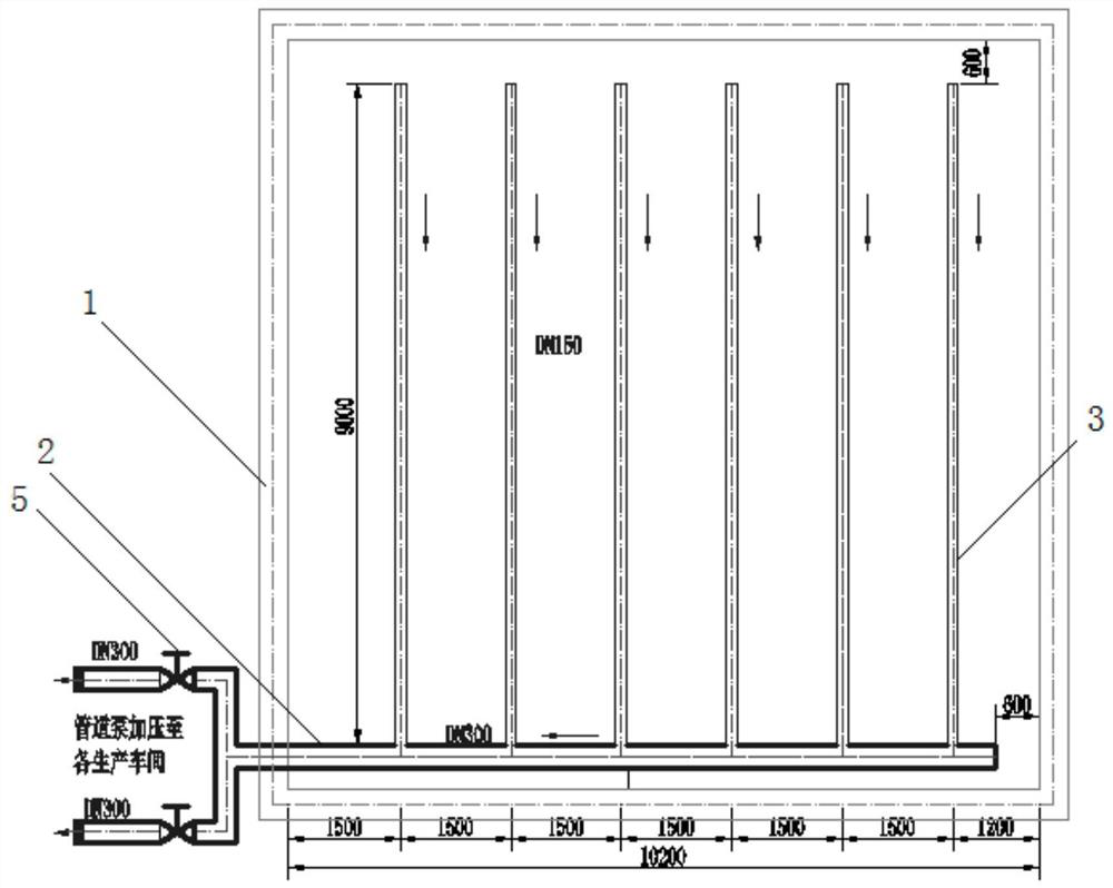
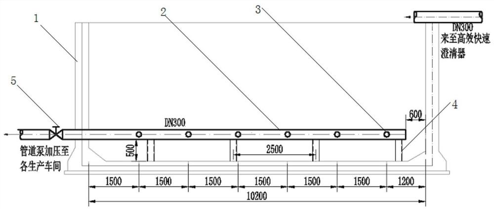
[0017] An automatic dredging clear water pool of a gravel production wastewater treatment system according to the present invention comprises: a clean water pool body 1, a main water pipe 2 installed through the bottom of the clean water pool body 1, a water branch pipe 3 connected with the main water pipe 2, and a main water pipe 2 And the water branch pipe 3 and the inner wall of the clear water tank body 1 are not in contact with each other at a distance, and the water branch pipe 3 is provided with a water inlet 31, and the water body flows into the water branch pipe 3 through the water inlet 31 in the cavity of the clear water tank body 1 Discharge through main water pipe 2.

[0018] The clear water pool body 1 is a cavity with equal length and width, and the distance between the cav...


PUM


Abstract

The invention discloses an automatic dredging and clear water pool of a sandstone production wastewater treatment system and a method for using it, comprising: a clear water pool body, a main water pipe installed at the bottom of the clear water pool body, a water branch pipe connected to the main water pipe, a main water pipe and a water tank. There is a distance between the branch pipe and the inner wall of the clear water tank body. The water branch pipe is provided with a water inlet hole. The flow rate of water pipe drainage is Q=300m 3 / h, clean water is discharged through the main water pipe at a flow rate of 1.2m / s; greater than the settling velocity of the largest solid particle of 0.07m / s, the settling velocity of solid particles in the clean water tank as a whole is much lower than the water flow velocity, ensuring that the entire production The bottom water of the clear water tank body has no dead angle in the flow, and the suspended matter does not sink to the bottom, so as to realize automatic dredging, which solves the problem that sedimentation occurs in the clear water tank of the existing sand and gravel production wastewater treatment system to block the water inlet of the pipeline pump.

Description

technical field [0001] The invention relates to an automatic desilting and clearing pool of a waste water treatment system for sand and gravel production and a use method thereof, and belongs to the technical field of waste water treatment for sand and gravel production. Background technique [0002] The traditional waste water treatment system of the gravel production line is the system recorded in the two-stage centrifugal desliming process disclosed in the Chinese patent No. 201110101333X applied by the unit; since the water treated by the vertical flow clarifier and the high-efficiency fast clarifier directly flows into the Clear water pool, and the clear water pool adopts a single-pipe water outlet method. The outlet pipe is located at a corner of the pool, and cannot pump water to the entire pool bottom at the same time, causing a large amount of suspended matter and fine particles in the water to settle at the bottom of the clear water pool. When there are too many pa...

Claims


Application Information

Patent Timeline
Patent Type & Authority Patents(China)
IPC IPC(8): B01D21/02B01D21/00
CPCB01D21/02B01D21/0006
Inventor 张昌晶严章国陈中华康未嘉王忠钱明华张健谢刚毛建
Owner SINOHYDRO BUREAU 9
Why Eureka
Try Eureka