Pressing pop-up device and application thereof

A pop-up device, flexible technology, applied in applications, household refrigeration devices, cooling fluid circulation devices, etc., can solve the problems of products that cannot be used for revolving doors, cannot be used for revolving doors, and are difficult to apply in a wide range, etc., to achieve the overall structure Smooth operation, convenient door opening and high application value

Pending Publication Date: 2022-03-11
CHANGHONG MEILING CO LTD
View PDF10 Cites 0 Cited by
  • Summary
  • Abstract
  • Description
  • Claims
  • Application Information

AI Technical Summary

Problems solved by technology

The patent is to push the door body by pressing the door body to trigger the pop-up structure. This structure is designed based on the slide rail and cannot be applied to products that swing the door.
[0005] Aiming at the problems mentioned above that the structure is relatively complex, the installation position is limited, the use noise is loud, the cost is high, and it is difficult to obtain a wide range of applications; and it cannot be applied to products that rotate to open the door; Devices and their applications

Method used


Image

  • Pressing pop-up device and application thereof
  • Pressing pop-up device and application thereof
  • Pressing pop-up device and application thereof

Examples


Embodiment 1

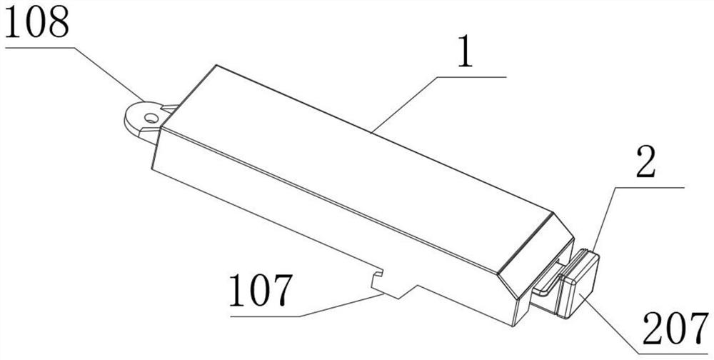
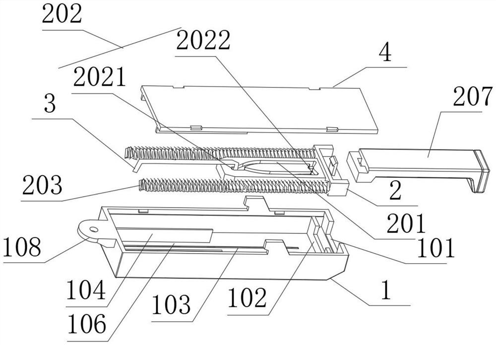
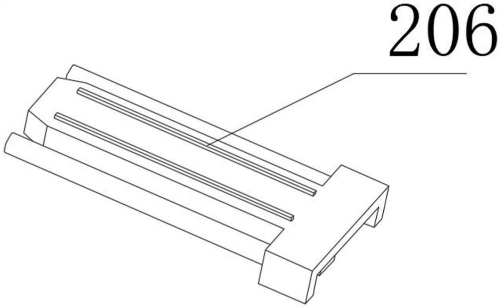
[0043] see Figure 1-5 As shown, the present invention is a pressing and ejecting device, including a base 1 and an elastic sliding seat assembly 2; the base 1 is a base for fixed installation; the elastic sliding seat assembly 2 is used for intermittent ejection to the push rod The power assembly, the ejector rod pushes the door body to achieve the effect of opening the door; the elastic sliding seat assembly 2 is slidingly matched with the base 1; One end is rotationally matched with the base 1; the elastic sliding seat assembly 2 is provided with a channel 201 for sliding cooperation with the other end of the guide column 3; the channel 201 is used for the other end of the guide column 3 to slide in one direction. In the closed slideway, two sliding slots 202 for sliding in and out of the other end of the guide column 3 are also arranged in the groove 201; springs 203 and springs 203 and Guide rod 204; guide ribs 206 are arranged on the back of the elastic sliding seat ass...

Embodiment 2

[0046] Carry out optimal technical scheme on the basis of embodiment one, please refer to Figure 9 As shown, the outer wall of one end of the base 1 is provided with a notch 101 for sliding fit with the elastic sliding seat assembly 2; the inner side of one end of the base 1 is provided with a baffle 102; The slider guide groove 103; the base 1 is fixed with two limit ribs 104 on both sides of the slider guide groove 103; Limiting; a spring accommodating groove 109 for placing the spring 203 is formed between an opposite outer surface of the two limiting ribs 104 and the inner wall of the base 1; The sliding groove 106 is in sliding fit with the elastic sliding seat assembly 2 .

Embodiment 3

[0048] Carry out preferred technical scheme on the basis of embodiment two, please refer to Figure 6-7 As shown, the outer end of the elastic sliding seat assembly 2 is provided with a push rod buckle 205; a push rod 207 is installed on the push rod buckle 205; .


PUM


Abstract

The invention discloses a pressing pop-up device and application thereof, and relates to the technical field of household appliances. The device comprises a base and an elastic sliding seat assembly, the base is a base for fixed installation; the elastic sliding seat assembly is a power assembly used for carrying out interval pop-up action on the ejector rod. The elastic sliding seat assembly is in sliding fit with the base; a guide sliding column is arranged between the base and the elastic sliding base assembly in a matched mode. One end of the guide sliding column is in running fit with the interior of the base; a channel is formed in the elastic sliding seat assembly; the channel is a closed slide way used for guiding the other end of the sliding column to slide in a one-way mode, and two sliding clamping grooves are further formed in the channel. Through the action of the base and the elastic sliding seat assembly, the relatively simple structure technical scheme realizes the effects of pushing the door body and opening the door, and has the advantages that the cost is low, the opening mode of the refrigerator door body is more convenient, and the use experience of a user is improved.

Description

technical field [0001] The invention belongs to the technical field of home appliances, and in particular relates to a push-and-eject device and an application thereof. Background technique [0002] With the improvement of people's living standards, there are higher and higher requirements for the convenience of household items. As the most frequently used household appliance, refrigerators are more complicated to use, especially when both hands are occupied, the operation of opening the door body becomes more inconvenient. [0003] Among them, the Chinese patent "Clutch Automatic Door Opener and Refrigerator", the publication number is CN109708399B; discloses a clutch automatic door opener and a refrigerator, the clutch automatic door opener includes a base, a drive source, a push rod and is arranged on the drive The transmission assembly between the source and the push rod, the push rod is movably installed on the base, the transmission assembly includes a central shaft f...

Claims


Application Information

Patent Timeline
IPC IPC(8): F25D23/02
CPCF25D23/028F25D2323/02
Inventor 田亚明李乾坤
Owner CHANGHONG MEILING CO LTD
Why Eureka
Try Eureka