Parallel computing method and system for electromagnetic environment around power transmission line

A transmission line and electromagnetic environment technology, applied in the direction of calculation, computer-aided design, design optimization/simulation, etc., can solve problems such as many parameters, long transmission line distance, difficult calculation, etc., to speed up the calculation process, accurate calculation results, The effect of improving computational efficiency

Pending Publication Date: 2022-03-11
STATE GRID CHONGQING ELECTRIC POWER CO ELECTRIC POWER RES INST +1
View PDF0 Cites 0 Cited by
  • Summary
  • Abstract
  • Description
  • Claims
  • Application Information

AI Technical Summary

Problems solved by technology

[0004] The present invention aims to at least solve the problem of long transmission line distance, wide coverage and inconvenient field measurement method in the prior art. The existing method only calculates the influence of the transmission line in the space, and the grounding structure of the space around the transmission line , ungrounded structures, and various buildings will also affect the electromagnetic environment in the space, and the calculation results are not accurate enough to reflect the real situation of the electromagnetic environment in the space; and the electromagnetic environment in the space around the transmission line is formed by the superposition of various factors. One of the technical problems that are difficult to calculate quickly due to the large number of parameters

Method used


Image

  • Parallel computing method and system for electromagnetic environment around power transmission line
  • Parallel computing method and system for electromagnetic environment around power transmission line
  • Parallel computing method and system for electromagnetic environment around power transmission line

Examples


Embodiment Construction

[0046] In order to understand the above-mentioned purpose, features and advantages of the present invention more clearly, the present invention will be further described in detail below in conjunction with the accompanying drawings and specific embodiments. It should be noted that, in the case of no conflict, the embodiments of the present application and the features in the embodiments can be combined with each other.

[0047] In the following description, many specific details are set forth in order to fully understand the present invention. However, the present invention can also be implemented in other ways than described here. Therefore, the protection scope of the present invention is not limited by the specific implementation disclosed below. Example limitations.

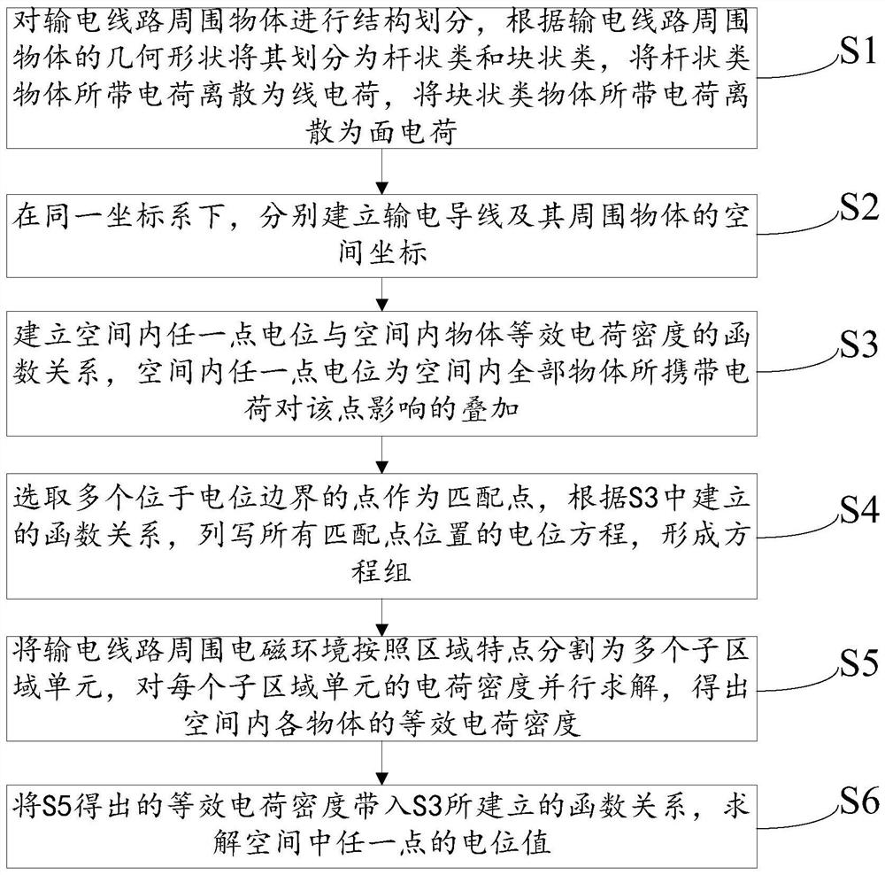
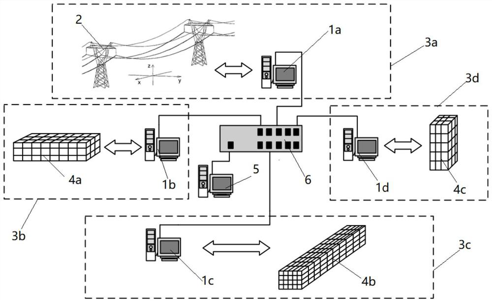
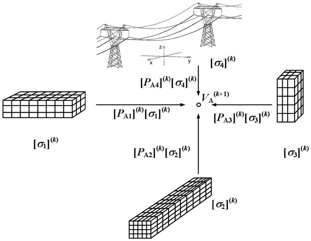
[0048] Refer below Figure 1 to Figure 4 A method for parallel calculation of the electromagnetic environment around a transmission line provided according to some embodiments of the present invention will b...


PUM


Abstract

The invention provides a parallel computing method and system for an electromagnetic environment around a power transmission line. The method comprises the following steps: carrying out structure division on objects around the power transmission line; in the same coordinate system, respectively establishing space coordinates of the power transmission conductor and surrounding objects; establishing a function relationship between the potential of any point in the space and the equivalent charge density of an object in the space; selecting a plurality of points located at the potential boundary as matching points, listing potential equations of all matching point positions, and forming an equation set; the method comprises the following steps: dividing an electromagnetic environment around a power transmission line into a plurality of sub-region units according to region characteristics, and solving the charge density of each sub-region unit in parallel to obtain the equivalent charge density of each object in a space; the obtained equivalent charge density is substituted into the established function relation, and the potential value of any point in the space is solved; the system comprises a sub-computing system and a data exchange unit. Objects in the space around the power transmission line are comprehensively considered, parallel calculation is adopted, the calculation efficiency is high, and the result is accurate.

Description

technical field [0001] The invention relates to the technical field of transmission line parameter detection, in particular to a parallel calculation method and system for the electromagnetic environment around the transmission line. Background technique [0002] In the context of national development, the country's electricity demand continues to increase, my country's energy distribution is uneven, energy needs to be transported across regions, and electric energy has become the object of choice. In the transmission of electric energy, the voltage level is high, and the electromagnetic environment around the transmission line is complex, which affects the lives of residents around the transmission line. It is necessary to calculate the voltage of the space area around the transmission line. [0003] Existing methods for measuring the space potential of transmission lines usually require manual or mechanical measurements on the spot. The transmission line has a long distan...

Claims


Application Information

Patent Timeline
IPC IPC(8): G06F30/10G06F30/20G06F113/16
CPCG06F30/10G06F30/20G06F2113/16
Inventor 徐禄文杨勃王谦宋伟李永福宫林邱妮李龙龙英凯杨华夏
Owner STATE GRID CHONGQING ELECTRIC POWER CO ELECTRIC POWER RES INST
Why Eureka
Try Eureka