
Crank arm forming die

A forming mold and curved arm technology, applied in the field of curved arm forming molds, can solve problems such as low production efficiency and complex forming and bending process, and achieve the effects of reducing production costs, improving injection molding efficiency, and increasing competitiveness

Pending Publication Date: 2022-03-15
JIANGSU RONGTENG PRECISION COMPONENTS
View PDF0 Cites 0 Cited by
  • Summary
  • Abstract
  • Description
  • Claims
  • Application Information

AI Technical Summary

Problems solved by technology

Injection molding is to heat and melt plastic (usually pellets) in the barrel of the injection molding machine. When it is in a flowing state, under the pressure of the plunger or screw, the molten plastic is compressed and moved forward, and then passes through the front section of the barrel. The nozzle is injected into the closed mold with low temperature at a very fast speed, formed, cooled, solidified in the cavity, and the product is obtained after demoulding. The existing curved arm forming mold has problems such as complicated forming and bending process and low production efficiency.

Method used


Image

  • Crank arm forming die
  • Crank arm forming die
  • Crank arm forming die

Examples


Embodiment Construction

[0017] The following will clearly and completely describe the technical solutions in the embodiments of the present invention. Obviously, the described embodiments are only some of the embodiments of the present invention, rather than all the embodiments. Based on the embodiments of the present invention, all other embodiments obtained by persons of ordinary skill in the art without making creative efforts belong to the protection scope of the present invention.

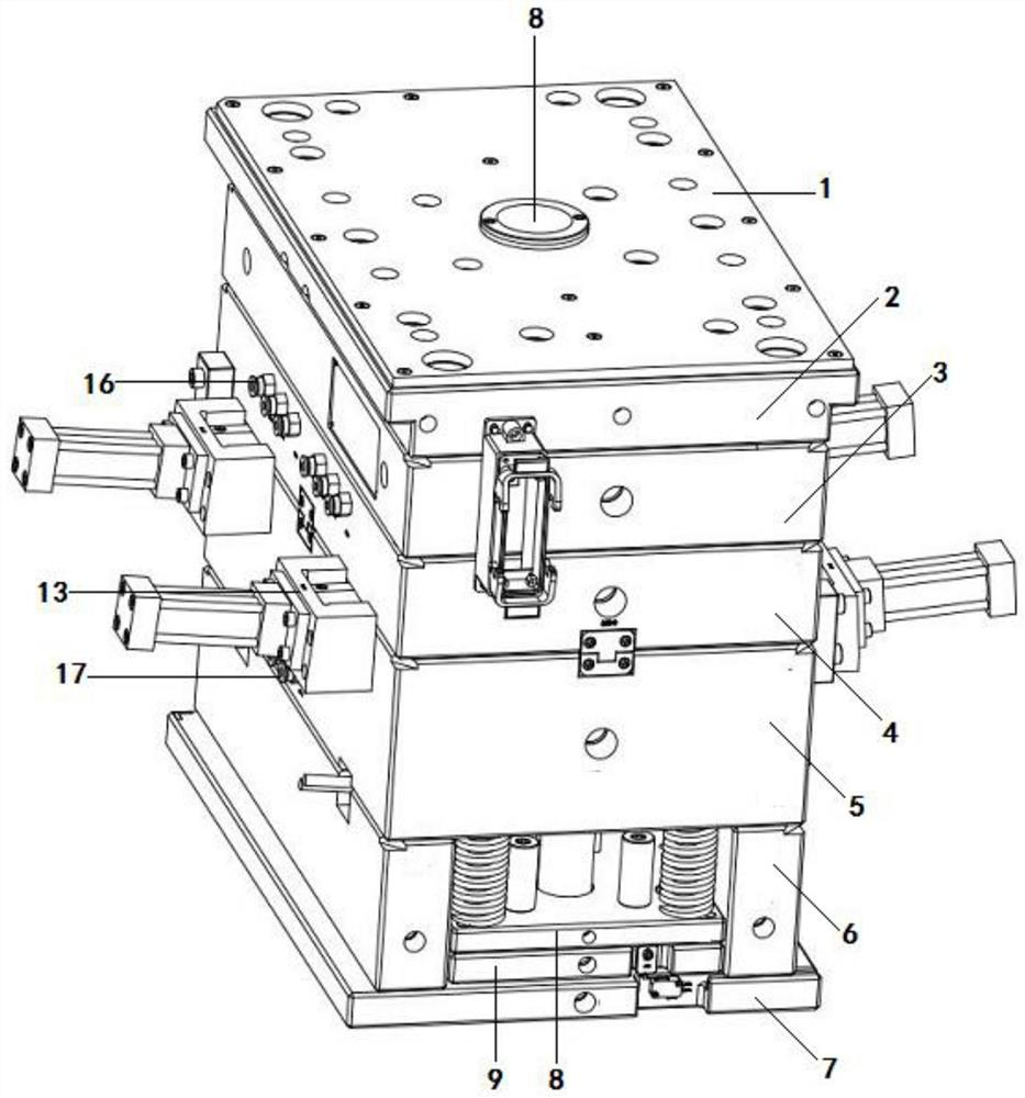
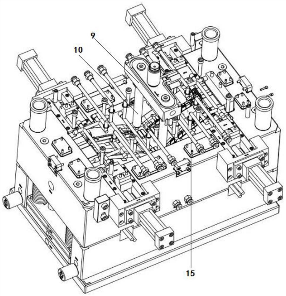
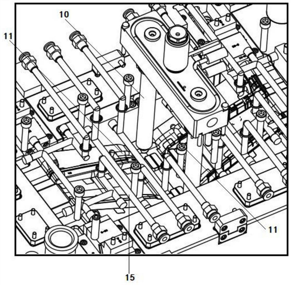
[0018] see Figure 1-4 , a crank arm molding die according to the present invention, comprising: a heat insulation plate 1, an upper fixing plate 2, a hot runner plate 3, an upper mold plate 4, a lower mold plate 5, two lower mold feet 6 and The lower fixing plate 7, the lower part of the upper formwork is positioned correspondingly with the guide sleeve on the lower formwork through the guide column, the upper formwork is provided with an upper mold core, and the lower formwork is relatively provided with a lower mo...


PUM


Abstract

The crank arm forming mold comprises a heat insulation plate, an upper fixing plate, a hot runner plate, an upper mold plate, a lower mold plate, two lower mold feet and a lower fixing plate which are sequentially and correspondingly arranged from top to bottom, the lower portion of the upper mold plate and a guide sleeve on the lower mold plate are correspondingly positioned through a guide column, and an upper mold core is arranged on the upper mold plate; an upper mold core is oppositely arranged on the upper mold plate, a lower mold core is oppositely arranged on the lower mold plate, an injection molding opening is formed in the heat insulation plate and connected with a main hot runner, the main hot runner is divided into two branch hot runners, the branch hot runners are connected with the middle of a cold runner, and the two ends of the cold runner are connected with a mold cavity defined by the upper mold core and the lower mold core correspondingly; an oil cylinder is arranged on the side edge of the lower die plate, a shaping piece is arranged at the output end of the oil cylinder, and the oil cylinder drives the shaping piece to stretch into the die cavity to assist forming of the crank arm. According to the mold, injection molding of four sets of crank arm products can be completed at the same time, the injection molding efficiency is improved, and the production cost is saved.

Description

technical field [0001] The invention relates to the technical field of mold processing and manufacturing, in particular to a crank arm forming mold. Background technique [0002] Injection molding is the most common molding method in the production of thermoplastic products. The mold used is a plastic injection mold, referred to as an injection mold. The processing equipment corresponding to the injection mold is a plastic injection machine (also known as an injection molding machine). Injection molding is to heat and melt plastic (usually pellets) in the barrel of the injection molding machine. When it is in a flowing state, under the pressure of the plunger or screw, the molten plastic is compressed and moved forward, and then passes through the front section of the barrel. The nozzle is injected into the closed mold with low temperature at a very fast speed, formed, cooled, solidified in the cavity, and the product is obtained after demoulding. The existing curved arm fo...

Claims


Application Information

Patent Timeline
IPC IPC(8): B29C45/26
CPCB29C45/26B29C2045/2651
Inventor 程传文
Owner JIANGSU RONGTENG PRECISION COMPONENTS
Learn More