Compact multi-antenna structure capable of being automatically unfolded

An automatic unfolding, multi-antenna technology, applied to rotating antennas, suitable for antennas on movable objects, antennas, etc., can solve the situation where it is difficult to control the movement of the torsion spring mechanism in real time, the gear mechanism has no self-locking function, and the antenna is difficult to maintain stability Status and other issues, to achieve the effect of compact structure, good synchronization and simple structure

Pending Publication Date: 2022-03-15
中国船舶重工集团公司第七二三研究所
View PDF0 Cites 0 Cited by
  • Summary
  • Abstract
  • Description
  • Claims
  • Application Information

AI Technical Summary

Problems solved by technology

The torsion spring mechanism has the advantages of simple structure, small size, and light weight. However, for equipment with a large load, the torsion spring has insufficient torsion, low reliability, poor stability after deployment, and it is difficult to control the movement of the torsion spring mechanism in real time. , poor maneuverability
The gear mechanism has stable transmission and high reliability, but due to the small space of the missile-borne equipment, in order to improve the effective space of the equipment, the volume of the driving motor is severely limited, the output torque of the motor is small, and the rotational load of the equipment is large, so the gear mechanism A large transmission ratio is required, that is, multi-stage gears need to be designed to realize the rotation of the antenna
The gear mechanism with multi-stage transmission is complex in structure, high in design requirements, and takes up a lot of space; at the same time, the general gear mechanism has no self-locking function, and it is difficult for the deployed antenna to maintain a stable state during high-speed flight, so the gear mechanism is not suitable for this application. Missile equipment

Method used


Image

  • Compact multi-antenna structure capable of being automatically unfolded
  • Compact multi-antenna structure capable of being automatically unfolded
  • Compact multi-antenna structure capable of being automatically unfolded

Examples


Embodiment Construction

[0029] In order to make the purpose, technical solution and advantages of the present application clearer, the present application will be further described in detail below in conjunction with the accompanying drawings and embodiments. It should be understood that the specific embodiments described here are only used to explain the present application, and are not intended to limit the present application.

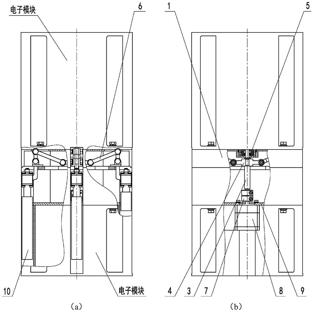
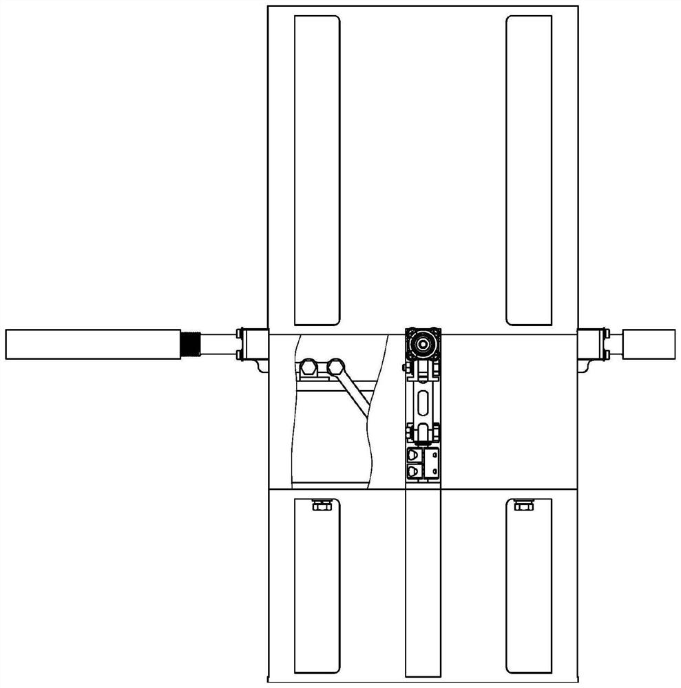
[0030] Such as figure 1 , figure 2 As described, a compact self-deployable multi-antenna structure includes:

[0031] Install base combination 1;

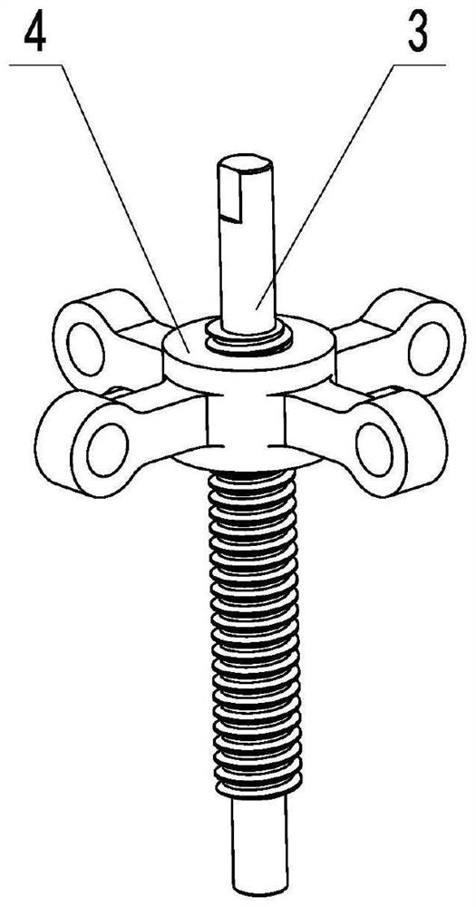
[0032] The screw mechanism fixed on the installation base assembly 1 through the bearing assembly 5; the screw mechanism includes a screw 3 and a nut 4, and the screw 3 is connected with the drive motor 8 through a coupling 7;

[0033] Four antenna units 10 connected to the nut 4 through the link mechanism 6; the antenna unit 10 and the link mechanism 6 are evenly distributed around the nut 4.

[0034] The present inventio...


PUM


Abstract

The invention provides a compact multi-antenna structure capable of being automatically unfolded. The compact multi-antenna structure comprises a mounting base combination, the screw mechanism is fixed on the mounting base assembly through a bearing assembly; the screw mechanism comprises a screw rod and a nut, and the screw rod is connected with a driving motor through a coupler; the four antenna units are connected with the nuts through connecting rod mechanisms; the antenna units and the connecting rod mechanism are uniformly distributed around the nut, the driving motor drives the screw rod to rotate, and the antenna units are unfolded from a vertical state to a horizontal state through linkage between the nut and the connecting rod mechanism. The invention has the advantages of large transmission ratio, compact structure, light weight, high reliability, strong load capacity, good synchronism and high rotation precision.

Description

technical field [0001] The invention relates to the structural design of missile-borne equipment, in particular to a compact multi-antenna structure that can be automatically expanded. Background technique [0002] With the development of science and technology and the improvement of military confrontation, the application fields of various guided weapon systems are constantly expanding, and missile-borne equipment has become a new research hotspot. For missile-borne equipment, its volume and weight are strictly limited, and the requirements for equipment reliability, environmental adaptability and vibration resistance are also very strict. [0003] The missile-borne equipment is mainly used to realize the detection and reception of radar signals. In order to realize the performance of the antenna with broadband and omnidirectional coverage at the same time, four broadband monopole antennas evenly distributed in 360° azimuth are used. Before the device is launched, it is in...

Claims


Application Information

Patent Timeline
Patent Type & Authority Applications(China)
IPC IPC(8): H01Q1/08H01Q1/12H01Q1/28H01Q21/00
CPCH01Q1/084H01Q1/12H01Q1/28H01Q21/00
Inventor 杭磊梁雪松马伟汤明春窦长安
Owner 中国船舶重工集团公司第七二三研究所
Why Eureka
Try Eureka