
A crane power assembly

A technology of power components and cranes, which is applied to transmission parts, transmission devices, running mechanisms, etc., can solve the problems of large size of the running mechanism, and achieve the effects of compact structure, improved circulation flow, and reliable heat dissipation

Active Publication Date: 2022-08-09
HENAN DONGQI MACHINERY
View PDF1 Cites 0 Cited by
  • Summary
  • Abstract
  • Description
  • Claims
  • Application Information

AI Technical Summary

Problems solved by technology

[0004] The purpose of the present invention is to provide a crane power assembly, which is used to solve the problem of large volume of the existing crane traveling mechanism

Method used


Image

  • A crane power assembly
  • A crane power assembly
  • A crane power assembly

Examples


Embodiment Construction

[0028] In the following, the present invention will be explained in detail with the implementation examples. It should be noted that in the case of non -conflict, the embodiments and the characteristics in the embodiments in the present invention can be combined with each other.

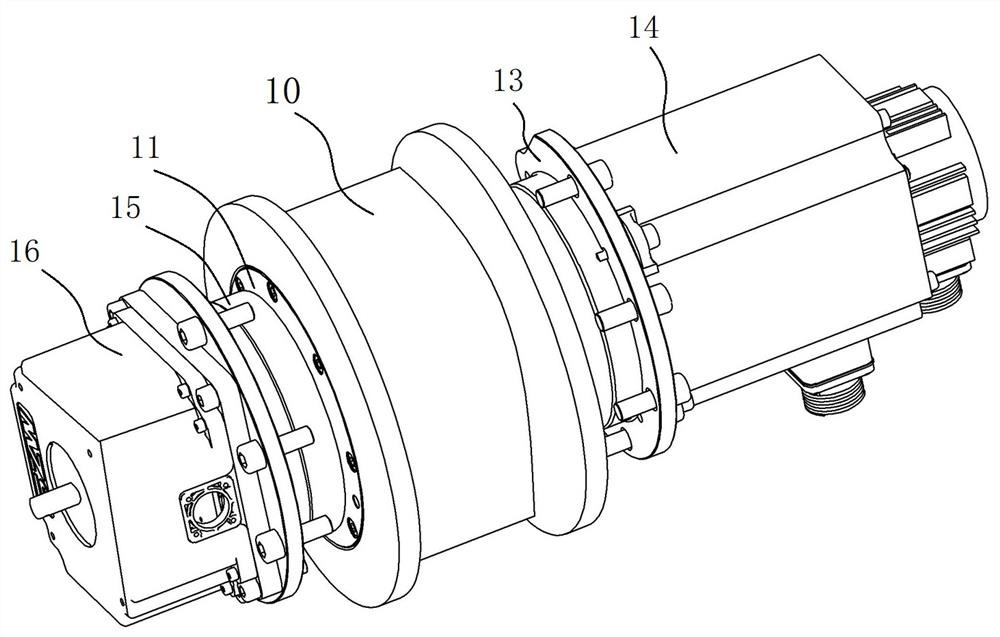
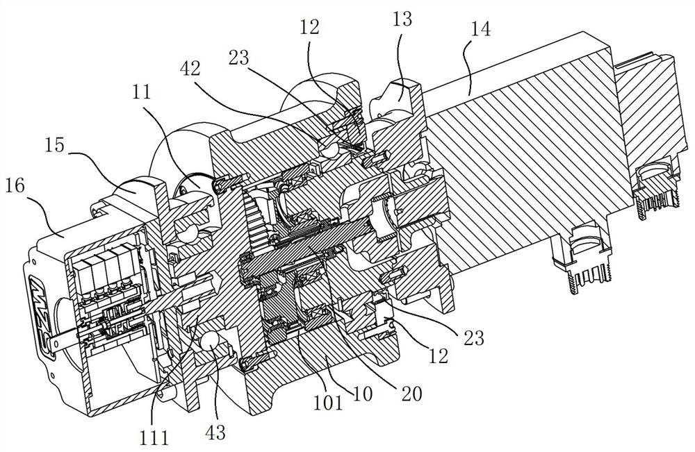
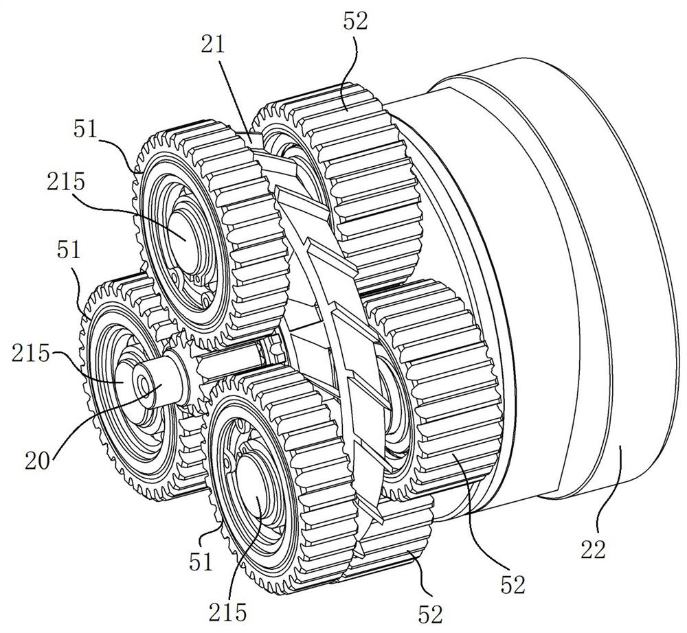
[0029] like Figure 1 to Figure 6 In an embodiment of the beeper power component of the present invention, the crane power component of the embodiment includes a cylindrical wheel 10, and a circular axial sealed end cover 11 on one side of the wheel 10, and the wheel 10 of the wheel 10. On the other side, a shaft block 12 is fixed on the other side. The inner surface of the wheel 10 has an inner gear 101, and the wheel 10 interior is equipped with a planet deceleration module. 21. Second -level planetary rack 22, first -level solar wheel 31 and secondary solar wheel 32, first -class planetary frame 21, and second -level planets on the planet wheels with the inner gear 101 of the wheel 10; One end can be r...


PUM


Abstract

The invention relates to a crane power assembly. The wheel comprises a cylindrical wheel hub, an inner gear ring is arranged on the inner surface of the wheel hub, and a planetary reduction module is installed in the wheel hub. The planetary reduction module includes a central rotating shaft, a first-level planet carrier, A secondary planetary carrier, a primary sun gear and a secondary sun gear, the primary planetary carrier and the planetary gear on the secondary planetary carrier mesh with the inner ring gear of the hub; one end of the central shaft is rotatable It is fixed at the center of the shaft seal end cover, the first-level planet carrier and the second-level sun gear are all sleeved on the central rotating shaft, and the second-level sun gear is fixedly connected with the first-level planet carrier. The spiral oil guide vane corresponding to the central shaft hole of the secondary sun gear; the application can effectively reduce the volume of the crane traveling mechanism; the spiral oil guide vane can make the lubricating oil on both sides of the secondary sun gear circulate axially, which can significantly improve the The circulating flow of lubricating oil in the wheel makes the lubrication and heat dissipation reliable during the rotation of the wheel.

Description

Technical field [0001] The present invention involves a lifting machinery technology, especially a crane power component. Background technique [0002] The classification of cranes is particularly widely classified. Common classifications include single beam cranes, double beam cranes, dragon gate cranes, bridge cranes, double -main Lianglongmen hanging, etc. In the beam -type crane and bridge cranes With a walking wheel, the driver motor drives the translation of the operating mechanism and walking mechanism through the reducer to drive the walking wheels. The existing crane walking wheels need to be equipped with a reducer to make the wheels larger and increase the difficulty of the crane structure design. [0003] For example, the Chinese patent document with the announcement number CN207569151U revealed a "drive wheel" for walking robots. The driver wheel hides the planetary reducer under the wheels, reducing the overall volume, making the structure more compact; Among the dr...

Claims


Application Information

Patent Timeline
Patent Type & Authority Patents(China)
IPC IPC(8): B66C9/14B66C9/08B66C13/16F16H1/32F16H1/28F16H57/023F16H57/029F16H57/04F16H57/08
CPCB66C9/14B66C9/08B66C13/16F16H57/023F16H57/029F16H57/0427F16H57/043F16H57/0412F16H57/0434F16H57/082F16H2001/289F16H2001/327F16H2057/02086F16H2057/085
Inventor 张春丽王立建刘文明赵朝云傅博韩明
Owner HENAN DONGQI MACHINERY
Learn More