Automatic anti-fog lens device, camera module and electronic device

A lens and anti-fog technology, applied in the field of lenses, can solve the problems of frosting or fogging on the surface of the camera lens, affecting the driving safety of the assisted driving or automatic driving system, affecting the image quality of the camera, etc. Fog problems, the effect of eliminating frosting and fogging

Pending Publication Date: 2022-03-15
TRULY OPTO ELECTRONICS
View PDF0 Cites 0 Cited by
  • Summary
  • Abstract
  • Description
  • Claims
  • Application Information

AI Technical Summary

Problems solved by technology

[0002] In the application of photography, security, industrial cameras and vehicle-mounted camera modules, it is often encountered that the surface of the camera lens is frosted or fogged due to changes in ambient temperature and humidity, which seriously affects the image quality of the camera, and even affects assisted driving or automatic control. The function of the driving system and then cause driving safety problems

Method used


Image

  • Automatic anti-fog lens device, camera module and electronic device
  • Automatic anti-fog lens device, camera module and electronic device
  • Automatic anti-fog lens device, camera module and electronic device

Examples


Embodiment 1

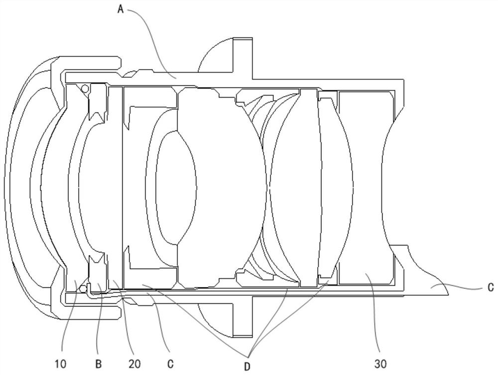
[0033] This embodiment provides a lens device, according to figure 1 ,include:

[0034] Lens barrel A;

[0035] A lens assembly, the lens assembly is arranged in the lens barrel A, the lens assembly includes a first lens 10, a second lens 20 and a third lens 30 arranged along the optical axis direction from the object end to the image end;

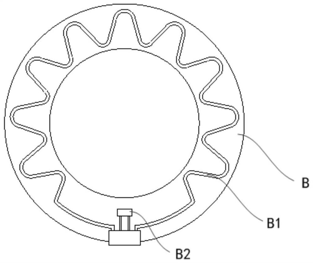
[0036] The annular printed circuit board B is arranged between the first lens 10 and the second lens 20 and is bonded to the edge of the first lens 10, and the annular printed circuit board B is arranged on one side surface of the first lens 10. There is a heating element B1 and a temperature sensing element B2, and the temperature sensing element B2 is used to obtain the temperature data of the first lens 10;

[0037] The flexible circuit board C is arranged on the side inner wall of the lens barrel A, and one end of the flexible circuit board C is electrically connected to the annular printed circuit board B, and the other end of the f...

Embodiment 2

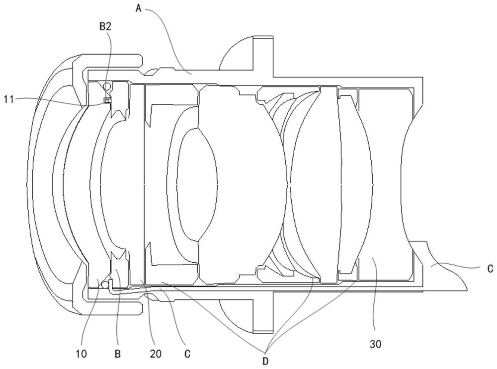
[0054] Embodiment 2 provides another lens device, which is different from Embodiment 1 in the placement position of the temperature sensing element B2.

[0055] Preferably, an accommodating hole 11 is provided at the edge of the surface of the image end side of the first lens 10, see image 3 , the accommodating hole 11 can accommodate the temperature sensing element B2; the position corresponding to the accommodating hole 11 on the annular printed circuit board B has a heat insulating layer, and the temperature sensing element B2 is arranged on the heat insulating layer, which can more accurately sense the first Whether the temperature of the outer surface of the lens 10 reaches the frosting temperature or the fogging temperature.

Embodiment 3

[0057] This embodiment provides a camera module, including the lens device provided in Embodiment 1-2 above.

[0058] This embodiment provides an electronic device, including the lens device provided in the foregoing embodiments 1-2.


PUM


Abstract

The invention provides an automatic anti-fog lens device, a camera module and an electronic device. The automatic anti-fog lens device comprises a lens barrel; the lens assembly is arranged in the lens barrel, and the lens assembly comprises a first lens, a second lens and a third lens which are arranged from the object end to the image end in the optical axis direction; the annular printed circuit board is arranged between the first lens and the second lens and attached to the edge of the first lens, and a heating element and a temperature sensing element are arranged on the surface of the side, facing the first lens, of the annular printed circuit board; the flexible circuit board is arranged on the inner wall of the side edge of the lens barrel, and one end of the flexible circuit board is electrically connected with the annular printed circuit board; and the control unit is electrically connected with the other end of the flexible circuit board. According to the invention, the heating element and the temperature sensing element are arranged, so that the frosting and fogging phenomena in the use of the lens can be well eliminated.

Description

technical field [0001] The invention relates to the field of lens technology, in particular to an automatic anti-fog lens device, a camera module and an electronic device. Background technique [0002] In the application of photography, security, industrial cameras and vehicle-mounted camera modules, it is often encountered that the surface of the camera lens is frosted or fogged due to changes in ambient temperature and humidity, which seriously affects the image quality of the camera, and even affects assisted driving or automatic control. The function of the driving system in turn leads to driving safety issues. Contents of the invention [0003] In view of the above problems, the present invention solves the lens frosting and fogging problems by designing a method capable of detecting the temperature of the lens group inside the lens body and supporting the realization of electric heating defrosting and defogging in the lens group. [0004] The present invention provi...

Claims


Application Information

Patent Timeline
Patent Type & Authority Applications(China)
IPC IPC(8): H04N5/225G03B17/55
CPCG03B17/55H04N23/52H04N23/57H04N23/55H04N23/54
Inventor 袁睿麟
Owner TRULY OPTO ELECTRONICS
Why Eureka
Try Eureka