
Clamp rapid switching trolley

A technology of fast switching and trolley, which is applied to trolleys, motor vehicles, multi-axis trolleys, etc. It can solve the problems that the fixture base cannot be locked and the guide mechanism cannot be moved to the base for guidance, so as to achieve accurate guide limit and lock Good effect and easy operation

Pending Publication Date: 2022-03-18
WUHU POWER TECH
View PDF0 Cites 0 Cited by
  • Summary
  • Abstract
  • Description
  • Claims
  • Application Information

AI Technical Summary

Problems solved by technology

But the actual fixture is on the pedestal. First, the switching mechanism needs to be locked with the pedestal of the fixture, and then the guide rail is extended to the pedestal to guide and transfer the fixture to the switching mechanism, and then the limit is fixed. This patent cannot be realized with the fixture pedestal. The lock is locked, and the guide mechanism cannot move to the pedestal so that it cannot be guided more smoothly, so it is very necessary to solve this problem

Method used


Image

  • Clamp rapid switching trolley
  • Clamp rapid switching trolley
  • Clamp rapid switching trolley

Examples


Embodiment Construction

[0024] In order to deepen the understanding of the present invention, the present invention will be further described below in conjunction with examples, which are only used to explain the present invention and do not constitute a limitation to the protection scope of the present invention.

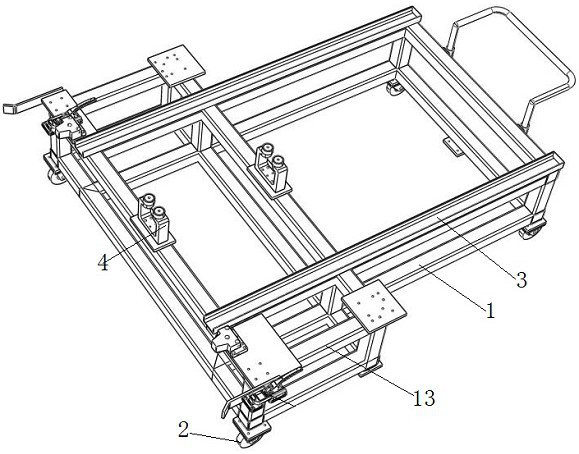
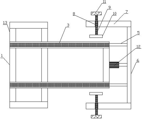
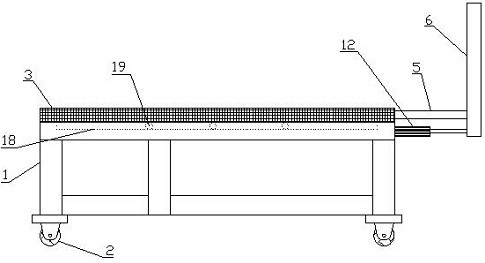
[0025] Such as Figure 1-5 As shown, this embodiment provides a fast clamp switching trolley, which includes a main body 1, universal wheels 2 are provided at the four corners of the bottom of the main body 1, and two locking mechanisms are provided on the left side of the top of the main body 1; the front and rear sides of the left end of the main body 1 An extension frame 13 is provided, and the front and rear locking mechanisms are respectively arranged on the front and rear extension frames 13; the locking mechanism includes a rotating locking arm 14 arranged on the extending frame 13, and the right end of the rotating locking arm 14 is movable A locking ring 15 is connected, and the ...


PUM


Abstract

The invention provides a quick clamp switching trolley, and belongs to the field of automobile welding clamps, universal wheels are arranged at four corners of the bottom of a body, and a front locking mechanism and a rear locking mechanism are arranged on the left side of the top of the body; front and back transverse guide rails with the same length are arranged at the top of the body; left and right guide wheel groups are arranged in the middle of the top of the body; extension rods extending out of the right sides of the two transverse guide rails are connected through a limiting plate, mounting arms are leftwards arranged at the front end and the rear end of the limiting plate, threaded holes penetrating front and back are formed in the mounting arms, threaded rods are installed in the threaded holes from outside to inside in a threaded mode, fixing plates are connected to the inner sides of the threaded rods, and rotating handles are arranged on the outer sides of the threaded rods. A transverse stepping motor is arranged on the right side of the body, the bottom end of the connecting plate is connected to the transverse stepping motor, and the guide rail can transversely move on the body. According to the clamping device, locking can be conducted firstly, then the guide rail is pushed to move leftwards for guiding, finally, the clamp is fixed, and operation is convenient.

Description

technical field [0001] The invention relates to the field of fixtures for automobile welding, in particular to a quick-switching trolley for fixtures. Background technique [0002] The fixtures of automobile OEMs or parts are not arranged on the ground. Some fixtures on the turntable or slide mechanism have a certain height from the ground. Generally, when changing fixtures, forklifts are used to fork them off directly, and then other fixtures are forked up. This operation Inconvenient and less efficient. The prior art patent CN111098249A discloses a device and method for quickly changing clamps, including a fixed plate, a clamp, a sliding plate, a push-pull guide rail, and a quick-plug joint assembly; at least one locking mechanism is arranged on the fixed plate; at least one A positioning pin hole, a fixture is installed on the bottom surface of the sliding plate; the sliding plate and the fixed plate are slidably matched through the push-pull guide rail; the quick-plug c...

Claims


Application Information

Patent Timeline
Patent Type & Authority Applications(China)
IPC IPC(8): B62B3/04B62B3/02B62B5/00B62B5/06
CPCB62B3/04B62B3/02B62B5/06B62B5/00
Inventor 王健陈一田邵家洪姚上前张欣
Owner WUHU POWER TECH
Learn More