Transformer protection device with monitoring function

A transformer protection and function technology, applied in transformer/inductor cooling, transformer/inductor components, fire alarms that rely on smoke/gas effect, etc., can solve problems such as affecting service life and lack of increasing transformer heat dissipation, To achieve the effect of increasing the rate of fire extinguishing

Active Publication Date: 2022-03-18
南通旭泰自动化设备有限公司
View PDF11 Cites 5 Cited by
  • Summary
  • Abstract
  • Description
  • Claims
  • Application Information

AI Technical Summary

Problems solved by technology

"However, this protection device lacks functional components to increase the heat dissipation of the transformer. When the heat of the transformer is too high, it will easily affect its service life.

Method used


Image

  • Transformer protection device with monitoring function
  • Transformer protection device with monitoring function
  • Transformer protection device with monitoring function

Examples


Embodiment 1

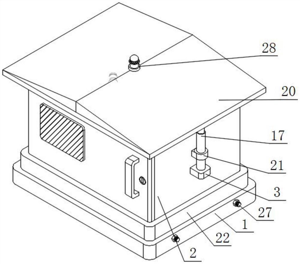
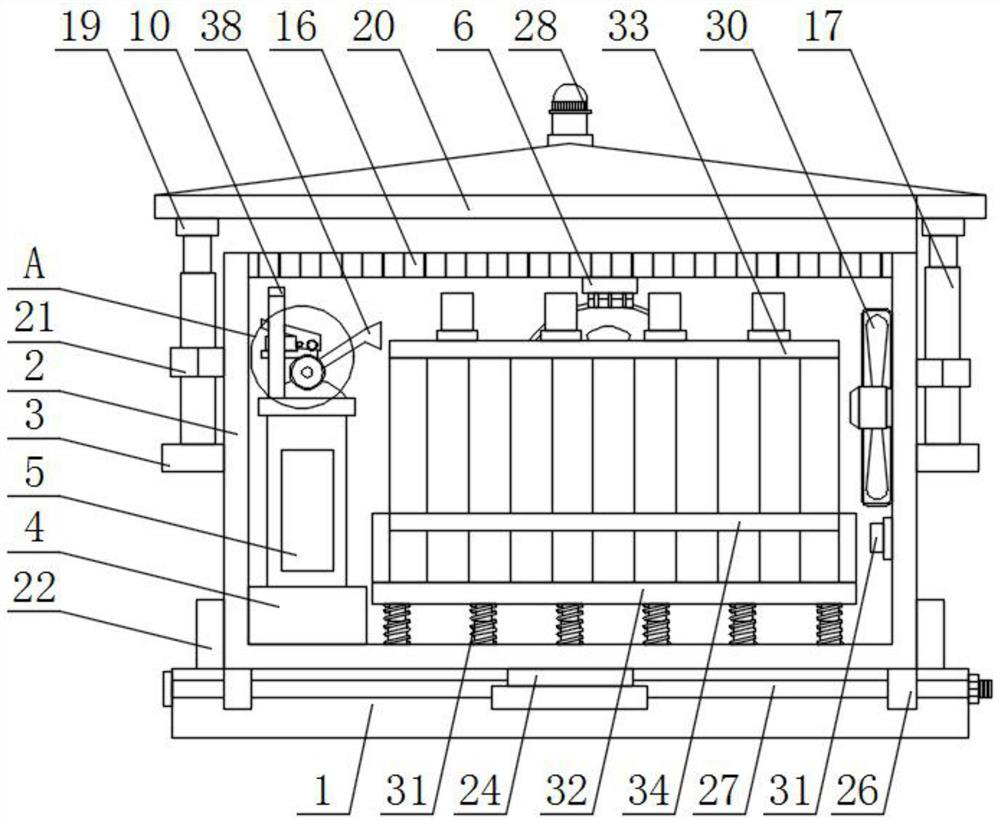
[0043] Such as figure 2 , image 3 , Figure 4 , Figure 6 and Figure 7 As shown, a transformer protection device with monitoring function includes a base 1, a protection box 2, a fixed plate 3, a long body frame 4 and a dry powder fire extinguisher bottle body 5, and a protection box 2 is installed on the top of the base 1, and the protection box 2 Both sides of the outer wall are equipped with fixed plates 3;

[0044] Specifically, the base 1 and the ground can be in a fixed connection state, which can provide a space for the protection box 2 to avoid direct contact between the protection box 2 and the ground, and at the same time facilitate the gravity sensor 24 to monitor the comprehensive gravity of the protection box 2. 2. Add a certain degree of protection for the transformer body 33 to avoid more interference from the outside world during its operation. The fixed plate 3 provides a place for the electric lifting rod 17 to be placed.

[0045] The bottom wall of t...

Embodiment 2

[0054] Such as figure 1 , figure 2 and Figure 5 As shown, the top of the protection box 2 is provided with multiple groups of evenly arranged through grooves 16, and the tops of the two groups of fixed plates 3 are equipped with electric lifting rods 17, and the tops of the electric lifting rods 17 are equipped with threaded discs 18, and the tops of the threaded discs 18 The outer surface is equipped with threaded cylinder 19, the top of two groups of threaded cylinders 19 is equipped with inclined top cover 20, the outer surface of electric lifting rod 17 is equipped with limiting cylinder 21, and the outer wall of one side of limiting cylinder 21 is attached to the outer wall of protection box 2 combine.

[0055] Specifically, when the top of the through groove 16 is not blocked, it can facilitate the discharge of hot air inside the protection box 2. When the electric lifting rod 17, the inclined top cover 20 and the protection box 2 are assembled, the electric lifting ...

Embodiment 3

[0057] Such as figure 2 and Figure 8 As shown, a square frame 22 is installed on the top of the base 1, and a fitting groove 23 is installed on the top of the base 1, and the fitting groove 23 is inside the enclosed space of the square frame 22, and the inner wall of the fitting groove 23 is installed with a gravity For the sensor 24, the top of the base 1 is provided with two groups of grooves 25 arranged side by side, and the grooves 25 are located on both sides of the fitting groove 23, and the bottom of the protective box 2 is equipped with two groups of long strips 26 arranged side by side, and the length The outer wall of the strip 26 fits the inner wall of the groove 25 , and two groups of fastening bolts 27 arranged front and back are installed on the outer wall of one side of the base 1 , and one end of the fastening bolt 27 runs through the inside of the two sets of long strips 26 .

[0058] An alarm 28 is installed on the top of the inclined top cover 20 , and th...


PUM


Abstract

The transformer protection device with the monitoring function comprises a base, a protection box, fixing plates, a long body frame and a dry powder extinguisher bottle body, the protection box is installed at the top of the base, and the fixing plates are installed on the outer walls of the two sides of the protection box; a long body frame is mounted on the bottom wall of the protection box, and a dry powder fire extinguisher bottle body is mounted on the bottom wall of the long body frame; a smoke sensor is installed on the top wall of the protection box, an air outlet pipe is installed at the top of the dry powder extinguisher bottle body, a pressing handle is installed at the top of the air outlet pipe, a fastening ring is installed on the outer surface of the dry powder extinguisher bottle body, two vertical rods arranged front and back are installed at the top of the fastening ring, and a transverse plate is installed at the tops of the two vertical rods. And an electric push rod is mounted at the bottom of the transverse plate. When the equipment is on fire, the equipment can extinguish fire autonomously, meanwhile, oxygen interruption is matched, the fire extinguishing efficiency is improved, the equipment can be cooled autonomously during use, and meanwhile, the equipment has an anti-taking function.

Description

technical field [0001] The invention relates to the technical field of protection devices, in particular to a transformer protection device with a monitoring function. Background technique [0002] The transformer is a device that uses the principle of electromagnetic induction to change the AC voltage. It is the basic equipment for power transmission and distribution. It is widely used in industry, agriculture, transportation, urban communities and other fields. When it is used outdoors, it is susceptible to external interference to reduce its own Therefore, it is self-evident to add protective devices to it. [0003] The defects of existing transformer protection devices are: [0004] 1. Patent document CN108281265A discloses an ignition transformer protection device, "including a detachable casing and a fixed bottom plate, a rubber hose is installed on the outside of the detachable casing, and the rubber hose runs through the detachable casing. There are fixed baffles o...

Claims


Application Information

Patent Timeline
Patent Type & Authority Applications(China)
IPC IPC(8): H01F27/40H01F27/08A62C3/16A62C31/02G08B3/10G08B17/10G08B21/24
CPCH01F27/402H01F27/085A62C3/16A62C31/02G08B17/10G08B21/24G08B3/10H01F2027/406
Inventor 奚一祥
Owner 南通旭泰自动化设备有限公司
Why Eureka
Try Eureka