
MTU adjusting method and device of data center network and computer equipment

A data center network and adjustment method technology, applied in the field of network transmission, can solve problems such as unreasonable MTU value setting, wrongly discarded ICMP packets, and packet loss, so as to reduce the pressure of operation and maintenance personnel, improve transmission stability, and reduce transmission The effect of delay

Pending Publication Date: 2022-03-18
INDUSTRIAL AND COMMERCIAL BANK OF CHINA
View PDF0 Cites 0 Cited by
  • Summary
  • Abstract
  • Description
  • Claims
  • Application Information

AI Technical Summary

Problems solved by technology

[0004] Since the data center carries a large number of different types of services, different services have different traffic characteristics, including delay-sensitive and throughput-sensitive types, and different link media also have different MTU values. It is impossible to ensure that the MTU values ​​​​of the devices at both ends are the same. It is easy to cause packet loss, and with the popularization of high-performance networks, the bandwidth reaches 25G or even 100G, and some specific applications such as NFS file systems also have the need to send large packets, so the network interface device set to the default value of MTU may not be suitable for data All business traffic in the center, and because PMTU relies on sending ICMP packets to determine its MTU, some firewalls mistakenly discard all ICMP packets, including packets required for PMTU to work normally, in order to denial of service attacks, resulting in MTU failure Find
[0005] Therefore, there is a problem in the prior art that data centers set unreasonable MTU values ​​for different business models

Method used

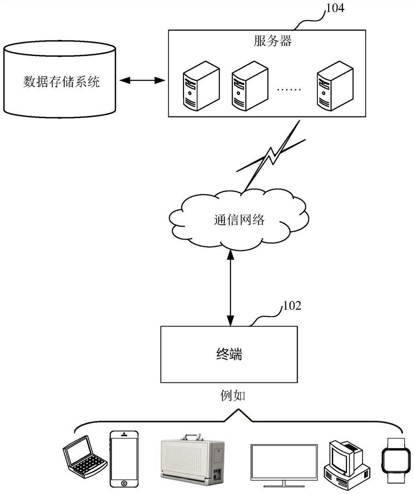

Image

  • MTU adjusting method and device of data center network and computer equipment
  • MTU adjusting method and device of data center network and computer equipment
  • MTU adjusting method and device of data center network and computer equipment

Examples


Embodiment Construction

[0050] In order to make the purpose, technical solution and advantages of the present application clearer, the present application will be further described in detail below in conjunction with the accompanying drawings and embodiments. It should be understood that the specific embodiments described here are only used to explain the present application, and are not intended to limit the present application.

[0051]The data center carries a large number of different types of services. Different services have different traffic characteristics, including delay-sensitive and throughput-sensitive types. Different link media also have different MTU values. It is impossible to ensure that the MTU values ​​​​of the devices at both ends are the same. Causes packet loss, and with the popularization of high-performance networks, the bandwidth reaches 25G or even 100G, and some specific applications such as NFS file systems also have the need to send large packets, so the network interface...


PUM


Abstract

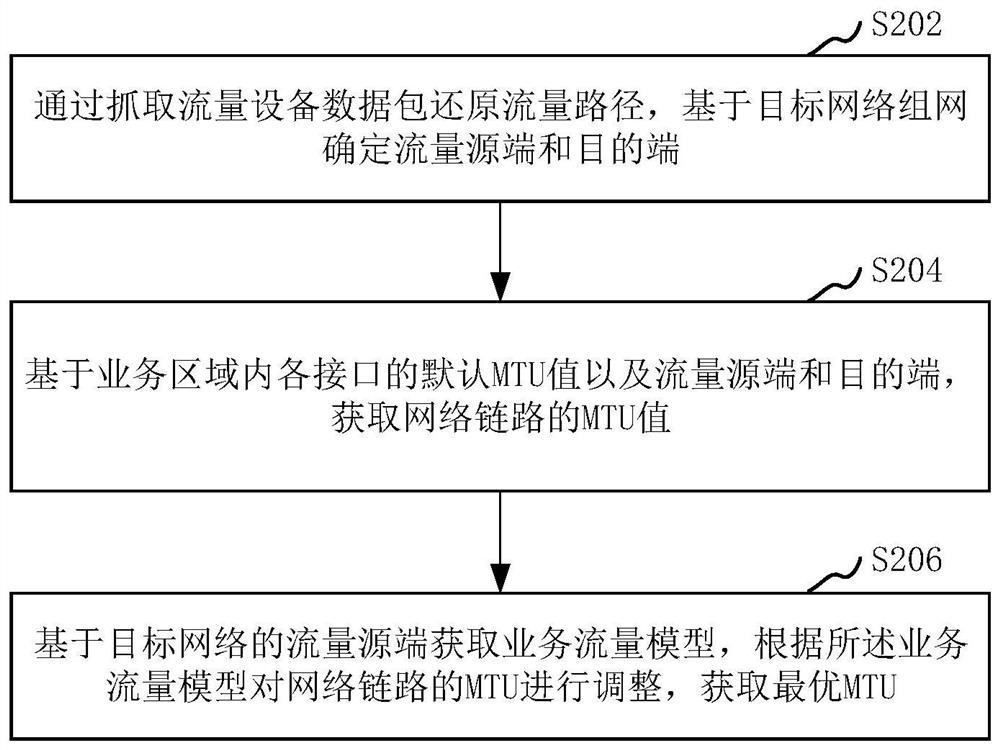
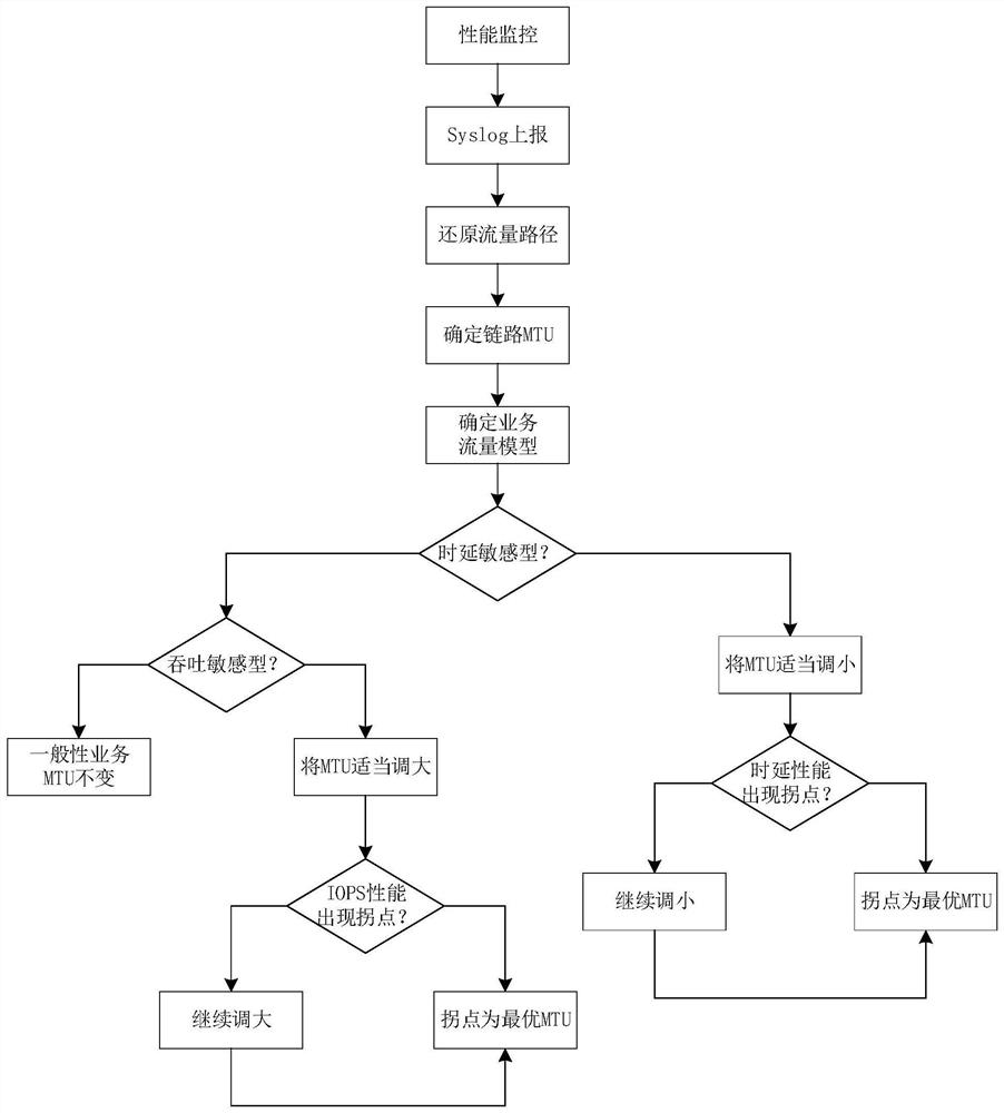
The invention relates to an MTU adjustment method and device of a data center network, computer equipment, a storage medium and a computer program product. The method comprises the following steps: restoring a traffic path by capturing a data packet of traffic equipment, and determining a traffic source end and a target end based on target network networking; obtaining an MTU value of a network link based on the default MTU value of each interface in the service area and a flow source end and a flow destination end; and obtaining a service flow model based on the flow source end of the target network, and adjusting the MTU of the network link according to the service flow model to obtain the optimal MTU. By adopting the method, the transmission efficiency can be improved or the transmission time delay can be reduced, the transmission stability can be improved, the traffic path change can be found in time, the link MTU can be intelligently and uniformly modified, and the pressure of operation and maintenance personnel is reduced.

Description

technical field [0001] The present application relates to the technical field of network transmission, and in particular to an MTU adjustment method, device, computer equipment, storage medium and computer program product of a data center network. Background technique [0002] The Maximum Transmission Unit (MTU) mainly refers to the maximum packet size for communication at the network layer. For some business area networks in the data center, in order to avoid excessive data packet fragmentation and being discarded, at the same time ensure that the sent data packets can be transmitted in all network devices. [0003] In the prior art, 1. Operation and maintenance personnel usually set the MTU value of each network device interface to a default value (Ethernet 1500, RoCE network 4200); 2. Use PMTU (PATH MTU, path MTU technology) to detect on the path The Maximum Transmission Unit of , which works by sending packets with the DF (Don't Fragment) option in the IP header set, an...

Claims


Application Information

Patent Timeline
IPC IPC(8): H04L47/36H04L41/14
CPCH04L47/365H04L41/145Y02D30/50
Inventor 杨飘飘余学山赵耀姜旭
Owner INDUSTRIAL AND COMMERCIAL BANK OF CHINA
Learn More