
Lens shadow correction method for camera imaging into circular picture and camera module

A technology of lens shadow and correction method, which is applied in the field of photography, can solve problems such as inability to guarantee consistency and inapplicability of circular image correction, achieve uniform color and brightness, and improve image effects

Pending Publication Date: 2022-03-18
TRULY OPTO ELECTRONICS
View PDF0 Cites 0 Cited by
  • Summary
  • Abstract
  • Description
  • Claims
  • Application Information

AI Technical Summary

Problems solved by technology

[0002] We all know that information such as people and scenery in the world is obtained by the camera module and displayed on the screen. The production and processing process of the camera module is actually a process of accumulation and combination of various functional materials. The camera module usually It is composed of lens, voice coil motor, infrared filter, photosensitive chip, PCB circuit board, etc. Since the stacking process of the camera module needs to use monomer materials with different functions, there is no guarantee between each monomer material. There is a good consistency. As end customers have higher and higher requirements for image effects, before the products are sold to consumers, the camera module will go through a process of debugging the image quality of the platform, but with the application Diversification. At present, in the products for shooting subtle applications, because the lens with strong magnification is used, the image is usually circular. When shooting the image, there will be vignetting around the image due to the reflection of the lens barrel diaphragm. The current platform shading correction (lens shading correction) is aimed at images with rectangular images and no dark corners, otherwise the corrected image will be abnormal, and it is not suitable for correction of circular images

Method used


Image

  • Lens shadow correction method for camera imaging into circular picture and camera module
  • Lens shadow correction method for camera imaging into circular picture and camera module
  • Lens shadow correction method for camera imaging into circular picture and camera module

Examples


Embodiment Construction

[0024] In order to make the purpose, technical solution and advantages of the present invention clearer, the technical solution of the present invention will be clearly and completely described below in conjunction with specific embodiments of the present invention and corresponding drawings. Apparently, the described embodiments are only some of the embodiments of the present invention, but not all of them. Based on the embodiments of the present invention, all other embodiments obtained by persons of ordinary skill in the art without making creative efforts belong to the protection scope of the present invention.

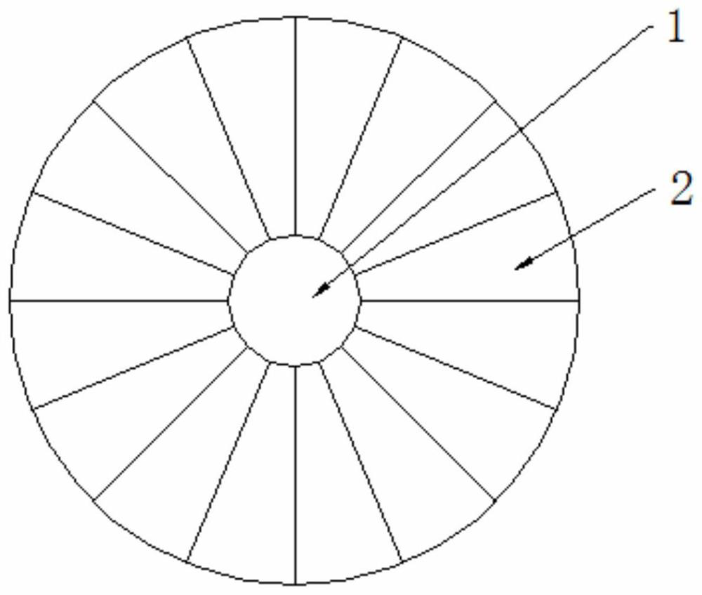
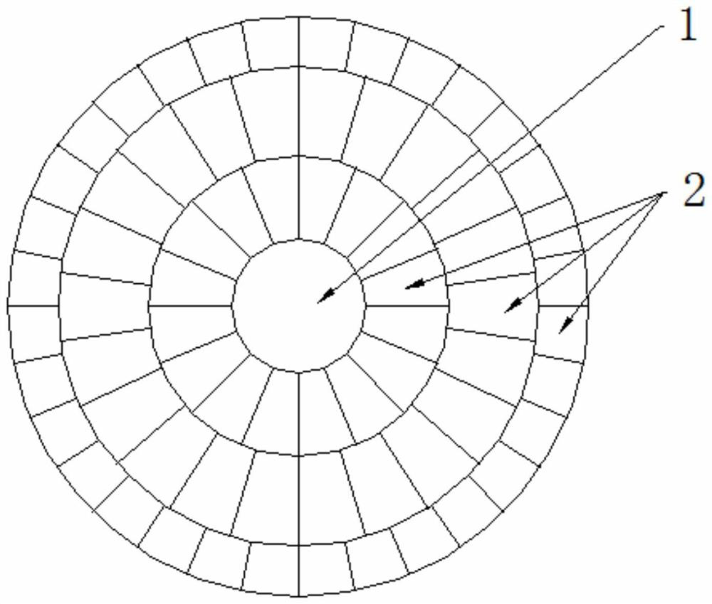
[0025] The invention relates to a lens shadow compensation correction method and a camera module for a circular image formed by a camera. The method of the invention is suitable for a circular camera module, and can perform shadow compensation on a circular image.

[0026] A lens shading correction method for a camera imaging a circular picture, specifically: divi...


PUM


Abstract

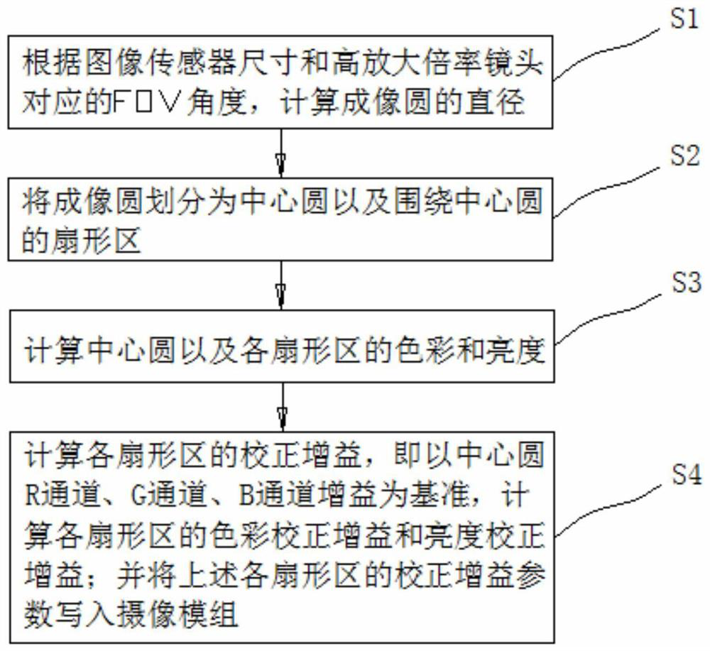
The invention discloses a lens shadow correction method for imaging a camera into a circular picture, which specifically comprises the following steps of: dividing an imaging circle into a central circle and fan-shaped regions surrounding the central circle, correcting the color and the brightness of each fan-shaped region by taking the color and the brightness of the central circle as references, and enabling the color correction gain to be the color of the central circle / the color of the fan-shaped regions, the brightness correction gain is the brightness of the center circle / the brightness of the fan-shaped region. According to the method, the shadow compensation area is divided for the circular imaging picture by adopting a mode of adding the central circle and the sector area, and color compensation and brightness compensation are adopted for the shadow area, so that the color and the brightness of the circular picture are uniform, no dark corner exists around the image, and the image effect is improved.

Description

technical field [0001] The invention belongs to the technical field of photography, and in particular relates to a lens shadow correction method and a camera module for imaging a circular picture by a camera. Background technique [0002] We all know that information such as people and scenery in the world is obtained by the camera module and displayed on the screen. The production and processing process of the camera module is actually a process of accumulation and combination of various functional materials. The camera module usually It is composed of lens, voice coil motor, infrared filter, photosensitive chip, PCB circuit board, etc. Since the stacking process of the camera module needs to use monomer materials with different functions, there is no guarantee between each monomer material. There is a good consistency. As end customers have higher and higher requirements for image effects, before the products are sold to consumers, the camera module will go through a proce...

Claims


Application Information

Patent Timeline
IPC IPC(8): H04N9/77H04N9/64H04N5/225
CPCH04N9/77H04N9/646H04N23/50
Inventor 吴光斯
Owner TRULY OPTO ELECTRONICS
Learn More