Retina imaging optical system with high resolution and coaxial illumination

A high-resolution, imaging optical technology, applied in the field of optical systems, can solve the problems of poor illumination uniformity, difficult data, archive management, etc., and achieve the effect of uniform imaging brightness, no vignetting, wide adaptability, and high resolution.

Active Publication Date: 2012-10-03
UNION OPTECH
View PDF0 Cites 0 Cited by
  • Summary
  • Abstract
  • Description
  • Claims
  • Application Information

AI Technical Summary

Problems solved by technology

[0002] At present, most of the fundus examinations are performed by doctors directly observing and examining the patient's eyes with the naked eye through the traditional ophthalmoscope, which has no objective contrast effect, and it is difficult to carry out data archiving and management
[0003] The traditional ophthalmoscope adopts non-coaxial illumination, and the illumination light path and the observation light path have a deflection angle, which leads to poor illumination uniformity and small observation angle, and the general observation angle is about 30 degrees. When used in the state of large pupils, patients are often required to dilate the pupils before examination
[0004] Traditional ophthalmoscopes use 10-20pcs lenses to adjust the focal length in segments for different eyeball sizes and diopters. It is inconvenient to manually turn the dial to switch between different magnifying glasses to adjust the focal length

Method used


Image

  • Retina imaging optical system with high resolution and coaxial illumination
  • Retina imaging optical system with high resolution and coaxial illumination
  • Retina imaging optical system with high resolution and coaxial illumination

Examples


Embodiment Construction

[0026] Below in conjunction with accompanying drawing and specific embodiment the present invention is described in further detail:

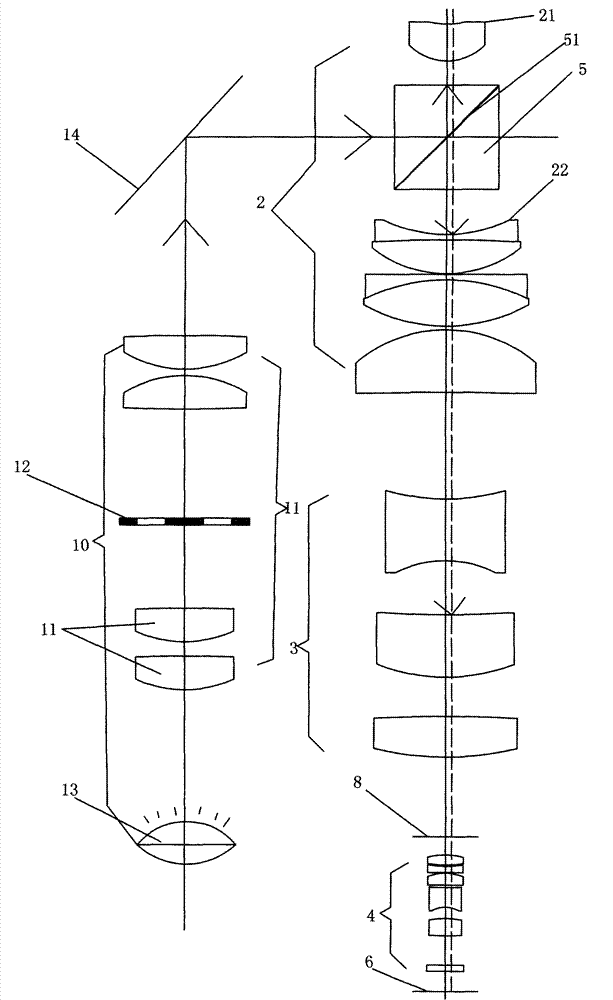
[0027] The retinal imaging optical system with high resolution and coaxial illumination can be used for photosensitive devices such as relatively high-pixel CMOS photosensitive sheets or ccd chips. It includes a first lens group 2 , a second lens group 3 , a third lens group 4 and a photosensitive chip 6 arranged sequentially on the common optical axis of the mirror side from the object direction. A stop 8 is provided between the second lens group 3 and the third lens group 4 .

[0028] Specifically, the focal length of the first lens 21 of the first lens group 2 close to the object side is positive. The overall focal length of the third lens group 4 is positive. The relative positions among the first lens group 2 , the second lens group 3 , and the photosensitive chip 6 are unchanged. The distance between the third lens group 4 and the first...


PUM


Abstract

The invention discloses a retina imaging optical system with high resolution and coaxial illumination, comprising a first lens group, a second lens group, a third lens group and a photosensitive chip, wherein the first lens group, the second lens group, the third lens group and the photosensitive chip are sequentially arranged from an objective direction to a lens direction by a common optical shaft; a diaphragm is arranged between the second lens group and the third lens group; and a semitransparent reflective mirror, which is used for transmitting part of rays and reflecting part of rays and forms an angle of 45 degrees with the optical shaft, is arranged between a first lens and a second lens in the first lens group, close to the objective direction. An illumination light path is arranged aside an imaging optical shaft, wherein the rays are reflected into the reflective mirror through a 45-degree reflective mirror surface. The invention provides the optical system with the characteristics of high resolution, large drawing angles, automatic focusing, convenient movement and coaxial illumination.

Description

【Technical field】 [0001] The invention relates to an optical system, which is a new type of optical system for photographing the fundus in medical examination. The optical system is composed of multiple lenses, prisms, reflectors, photosensitive chips and light sources. 【Background technique】 [0002] At present, most fundus examinations are performed by doctors directly observing and examining patients' eyes with the naked eye through traditional ophthalmoscopes. There is no objective comparison effect, and it is difficult to carry out data archiving and management. [0003] The traditional ophthalmoscope adopts non-coaxial illumination, and the illumination light path and the observation light path have a deflection angle, which leads to poor illumination uniformity and small observation angle, and the general observation angle is about 30 degrees. When the pupil is used in a state with a large pupil, the patient is often required to dilate the pupil for examination. [0...

Claims


Application Information

Patent Timeline
Patent Type & Authority Patents(China)
IPC IPC(8): A61B3/15A61B3/12
Inventor 邹文镔肖明志
Owner UNION OPTECH
Why Eureka
Try Eureka