Method and device for measuring grid frequency

A power grid frequency and power grid technology, applied in the field of signal processing, can solve the problems of power grid signal distortion, limited frequency accuracy, large tracking signal frequency error, etc., and achieve high-precision frequency measurement, excellent sidelobe attenuation characteristics, and suppression of spectrum leakage effect of ability

Active Publication Date: 2017-10-03
BEIJING SMARTCHIP MICROELECTRONICS TECH COMPANY +2
View PDF4 Cites 0 Cited by
  • Summary
  • Abstract
  • Description
  • Claims
  • Application Information

AI Technical Summary

Problems solved by technology

[0004] The first method is a method of solving the frequency in the time domain. The frequency of the periodic signal is calculated by calculating the time difference between two zero-crossing points. The frequency accuracy is mainly limited by the precise moment of the zero-crossing point. Due to the existence of noise, the zero-crossing point can be accurately judged. Restricted; secondly, the frequency accuracy is limited by the possibility of distortion of the grid signal, and errors will occur in calculating the frequency by using the zero-crossing point
[0005] The second method uses DFT spectrum analysis technology to calculate the frequency of the power grid. The disadvantage of this method is that it has high requirements for sampling and needs to track the frequency change of the signal. Once the frequency error of the tracking signal is large, the frequency accuracy will drop seriously, so the hardware requirements are relatively high.

Method used


Image

  • Method and device for measuring grid frequency
  • Method and device for measuring grid frequency
  • Method and device for measuring grid frequency

Examples


Embodiment Construction

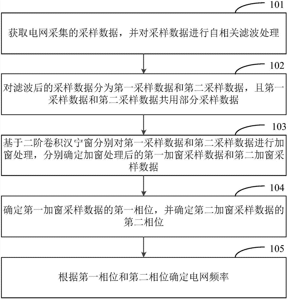
[0036] Below in conjunction with accompanying drawing, specific embodiment of the present invention is described in detail, but it should be understood that protection scope of the present invention is not limited by specific embodiment.

[0037]In order to make the purpose, technical solutions and advantages of the embodiments of the present invention clearer, the technical solutions in the embodiments of the present invention will be clearly and completely described below in conjunction with the drawings in the embodiments of the present invention. Obviously, the described embodiments It is a part of embodiments of the present invention, but not all embodiments. Based on the embodiments of the present invention, all other embodiments obtained by persons of ordinary skill in the art without creative efforts fall within the protection scope of the present invention. Unless expressly stated otherwise, throughout the specification and claims, the term "comprise" or variations th...


PUM


Abstract

The invention discloses a method and device for measuring grid frequency. The method comprises the following steps: obtaining sampling data collected by a power grid and carrying out auto-correlation filtering processing on the sampling data; dividing the filtered sampling data into first sampling data and second sampling data; carrying out windowing processing on the first sampling data and the second sampling data based on a second-order convolution Hanning window to determine first windowing sampling data and second windowing sampling data obtained after windowing processing respectively; determining a first phase of the first windowing sampling data and a second phase of the second windowing sampling data; and determining grid frequency according to the first phase and the second phase. The method adopts equal-data-length auto-correlation double filtering, so that in-band white noise can be filtered effectively, and SNR (signal to noise ratio) can be improved greatly; and through the second-order convolution Hanning window, spectral interference can be reduced greatly, and the method has a good signal-to-noise ratio and good spectral leak suppression ability.

Description

technical field [0001] The invention relates to the technical field of signal processing, in particular to a method and device for measuring grid frequency. Background technique [0002] The existing methods for measuring grid frequency mainly include the following three methods: the first one is to calculate the grid frequency by calculating the time difference between two zero-crossing points; the second one is to directly calculate the periodic signal frequency by using the spectrum analysis technology of synchronous sampling; the third one , using the time delay phase difference method based on DFT (Discrete Fourier Transform, Discrete Fourier Transform) to solve the frequency. [0003] In the course of realizing the present invention, the inventor finds that there are at least the following problems in the prior art: [0004] The first method is a method of solving the frequency in the time domain. The frequency of the periodic signal is calculated by calculating the t...

Claims


Application Information

Patent Timeline
Patent Type & Authority Applications(China)
IPC IPC(8): G01R23/165
CPCG01R23/165
Inventor 李建立陈河杨士明唐玉建高金鹏李涛刘瑞
Owner BEIJING SMARTCHIP MICROELECTRONICS TECH COMPANY
Why Eureka
Try Eureka