
Orthopedic surgery site tracker fixing device

A fixation device and orthopedic surgery technology, applied in the field of medical devices, can solve problems such as inability to meet the needs of orthopedic surgery, insufficient collection directions, and limited surgical operation space, so as to save surgical time, ensure integrity, and operate simply and quickly Effect

Pending Publication Date: 2022-03-22
HANGZHOU JOINTECH LTD
View PDF4 Cites 0 Cited by
  • Summary
  • Abstract
  • Description
  • Claims
  • Application Information

AI Technical Summary

Problems solved by technology

[0003] At present, there are mainly several fixation methods commonly used. The first one is to drive the bone needle into the bone, clamp the bone needle with two pieces of metal, and lock the metal with screws. One end of the metal has a threaded hole for Installing a tracker, although this method is simple and practical, does not limit the direction of the two locking metals, and requires the operator to be more patient. At the same time, the acquisition direction of the array is not comprehensive enough, which limits the operation space and increases the difficulty of the operation; the second method The method is to improve the clamping of the bone needle, and use it as a whole module, leaving two pin holes and a locking bolt, and the relative movement between the two locking metals can only be along one direction, and the other array connection On the one hand, some connecting rod structures are used, and only certain directions are taken, but if the operator loosens too much in this way, the whole structure will fall apart, which increases the risk; the third way is to use three bone needles, using triangular Stabilization to increase the stability of the immobilization device, but increases trauma
Therefore, the existing tracker fixation device cannot meet the needs of orthopedic surgery

Method used


Image

  • Orthopedic surgery site tracker fixing device
  • Orthopedic surgery site tracker fixing device
  • Orthopedic surgery site tracker fixing device

Examples


Embodiment Construction

[0029] The embodiment of the present invention will be described in further detail below in conjunction with the accompanying drawings and examples, and the accompanying drawings are used to illustrate the principles of the present invention, but cannot be used to limit the scope of the present invention, that is, the present invention is not limited to the described examples .

[0030] In the description of the present invention, it should be noted that, unless otherwise specified, the meaning of "many" is two or more; the terms "upper", "lower", "left", "right", "inside" The orientation or positional relationship indicated by , "outside" and so on are only for the convenience of describing the present invention and simplifying the description, and do not indicate or imply that the referred device or element must have a specific orientation, be constructed and operated in a specific orientation, and therefore cannot be understood To limit the present invention. In addition, ...


PUM


Abstract

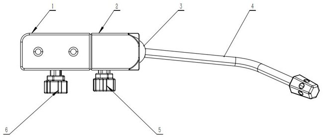
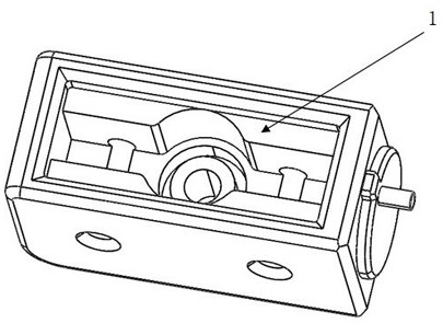
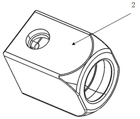
The invention relates to the technical field of medical instruments, in particular to an orthopedic surgery site tracker fixing device which comprises a fixing device main body, a fixing device auxiliary body outer frame, a fixing device rotating steel ball, a fixing device connecting rod, an auxiliary body knob and a main body knob. Through linkage of the main body knob, the main body locking bolt and the fixing device clamping module, clamping of double spicules is achieved, and operation is easy and convenient; through linkage of an auxiliary body knob, an auxiliary body locking bolt, an auxiliary body inclined wedge block and an auxiliary body bowl-shaped wedge block, clamping of a rotating steel ball of a fixing device is achieved, meanwhile, extrusion force and friction force are generated, the tracker is firmly fixed to the expected position, a hidden limiting pin exists in the tracker, it can be guaranteed that the locking bolt does not fall off, and the integrity of the tracker is guaranteed. In addition, due to the fact that movement paths of related movable parts are preset, for example, related parts of the bone needle clamping structure can only move linearly, and a ball head of the steel ball pressing structure can only rotate, operation of medical staff is more direct and simpler, and operation time is saved.

Description

technical field [0001] The invention relates to the technical field of medical devices, in particular to a fixation device for an orthopedic operation site tracker. Background technique [0002] In the existing orthopedic surgery assisted by surgical robots, a tracker composed of luminous or reflective markers arranged in a certain arrangement is an important positioning device and is an important part of orthopedic surgery. In order to achieve accurate positioning of the surgical site, the tracker needs to be fixed. [0003] At present, there are mainly several kinds of fixation methods commonly used. The first one is to drive the bone needle into the bone, clamp the bone needle with two pieces of metal, and lock the metal with screws. One end of the metal has a threaded hole for Installing a tracker, although this method is simple and practical, does not limit the direction of the two locking metals, and requires the operator to be more patient. At the same time, the acqu...

Claims


Application Information

Patent Timeline
Patent Type & Authority Applications(China)
IPC IPC(8): A61B34/20
CPCA61B34/20A61B2034/2059
Inventor 荣健
Owner HANGZHOU JOINTECH LTD
Learn More