Transfer bed and bed surface device therein

A transfer bed and bed board technology, applied in the field of transfer beds, can solve the problems of increasing the labor intensity of medical staff, the bed board cannot be removed, and the inconvenience of transferring patients, etc., and achieves the effects of reducing labor intensity, smooth movement, and reasonable installation structure.

Pending Publication Date: 2022-03-22
江苏永发医用设备科技股份有限公司
View PDF0 Cites 1 Cited by
  • Summary
  • Abstract
  • Description
  • Claims
  • Application Information

AI Technical Summary

Problems solved by technology

[0002] At present, the function of the traditional transfer bed is relatively single, and the bed board usually cannot be removed, which makes it inconvenient to transfer patients during the transfer process
Yes, although the bed board can also be moved, the patient still needs to be moved after it is moved out. On the one hand, the movement will cause harm to the patient, and on the other hand, it also increases the labor intensity of the medical staff.

Method used


Image

  • Transfer bed and bed surface device therein
  • Transfer bed and bed surface device therein
  • Transfer bed and bed surface device therein

Examples


Embodiment Construction

[0024] The specific implementation of the bed surface device in a transport bed according to the present invention will be described in detail below with reference to the accompanying drawings.

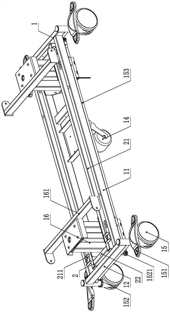
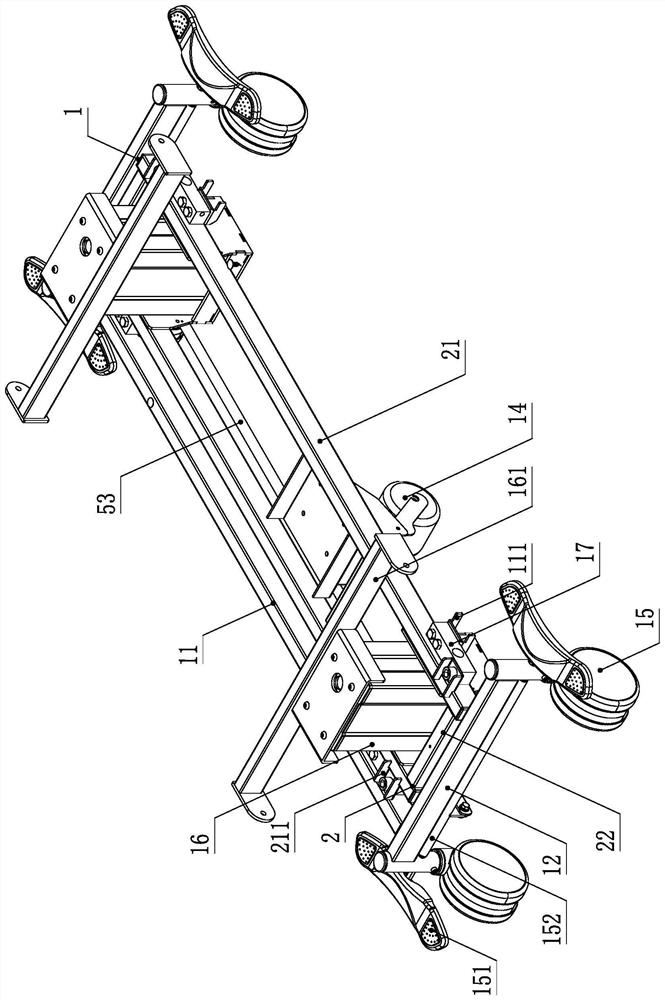
[0025] Such as Figure 1 to Figure 7As shown, the bed surface device in a transfer bed according to the present invention, its structure includes: a bed frame 3, and a bed board 5 that is slidably arranged on the bed frame 3, and the specific setting method is: the bed board 5 is placed on the Two guide columns 503 are respectively arranged at both ends of the follower side, and guide bearing rollers 504 are arranged on the guide columns 503, and guide chute frames corresponding to the guide bearing rollers 504 are arranged on the described bed frame 3 32, the guide bearing roller 504 is set in the corresponding guide chute frame 32 (belongs to the common technology in this field, and will not be described here); the bed board 5 is provided with a translation frame 4, the bed frame 3...


PUM


Abstract

The invention discloses a transfer bed and a bed surface device in the transfer bed. The bed surface device comprises a bed frame and a bed board arranged on the bed frame in a sliding mode. A translation frame is arranged on the back face of the bed board, a cloth cover rotating power device is arranged in the middle of the translation frame, transmission installation bases are arranged at the two ends of the translation frame respectively, a driving rod is arranged in the cloth cover rotating power device, and linkage rods are arranged at the two ends of the driving rod respectively. The ends of the linkage rods are movably arranged in the transmission installation bases at the corresponding ends and provided with driving wheels after extending out of the transmission installation bases, the pair of transmission installation bases is provided with a cloth cover rotating shaft and a pair of cloth cover guiding rods, and the cloth cover guiding rods are provided with a row of guiding idler wheels. The two ends of the cloth cover rotating shaft are arranged on the rotary guide mounting seats on the corresponding sides respectively, transmission wheels are arranged, and transmission parts are arranged on the transmission wheels and the driving wheels; and rotating cloth is wound on the bed plate and wound on the cloth cover rotating shaft. The bed surface device is particularly suitable for a transfer bed.

Description

technical field [0001] The invention relates to a transfer bed, in particular to a transfer bed and a bed surface device therein. Background technique [0002] At present, the function of the traditional transfer bed is relatively single, and the bed board usually cannot be removed, which makes it inconvenient to transfer the patient during the transfer process. Yes, although the bed board can also be moved, after moving out, the patient still needs to be moved, which will cause harm to the patient due to the movement on the one hand, and on the other hand, also increases the labor intensity of the medical staff. Contents of the invention [0003] The technical problem to be solved by the present invention is to provide a bed surface device in a transfer bed in which the bed board can be moved out and the patient can be sent out and the bed board can be moved back at the same time. [0004] In order to solve the above-mentioned technical problems, a technical solution ado...

Claims


Application Information

Patent Timeline
Patent Type & Authority Applications(China)
IPC IPC(8): A61G1/02A61G1/04A61G1/052A61G7/14
CPCA61G1/0212A61G1/04A61G1/052A61G7/103A61G7/1046
Inventor 张永发刘凯范士磊
Owner 江苏永发医用设备科技股份有限公司
Why Eureka
Try Eureka