Mining wet dust removal method

A wet dust removal and mining technology, applied in separation methods, chemical instruments and methods, dispersed particle separation, etc., can solve the problems of insufficient dust treatment, easy blockage of dust removal, and difficult maintenance of devices, and reduce the probability of secondary dust. , easy to maintain, to ensure the effect of cleaning

Pending Publication Date: 2022-03-22
林宏
View PDF2 Cites 0 Cited by
  • Summary
  • Abstract
  • Description
  • Claims
  • Application Information

AI Technical Summary

Problems solved by technology

[0006] Aiming at the deficiencies of the prior art, the present invention provides a mine-used wet dust removal method, which solves the problem of easy blockage during dust removal, and the device is not easy to maintain, and it is easy to cause secondary dust when the gas is discharged, and the dust treatment when the device is in use Not thorough enough, prone to residual problems

Method used


Image

  • Mining wet dust removal method
  • Mining wet dust removal method
  • Mining wet dust removal method

Examples


Embodiment 1

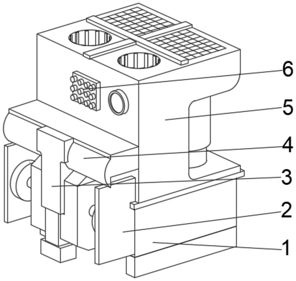
[0040] see Figure 1-6 , the present invention provides a technical solution: a wet dust removal method for mining, comprising a water storage tank 1, a circulation box 2 is fixedly connected to the top of the left outer wall of the water storage tank 1, and a water outlet is provided at the middle of the top of the left outer wall of the circulation box 2 The top of the pipe 3 and the water outlet pipe 3 are connected with the adjustment piece 4, and the outer wall of one side of the adjustment piece 4 is fixedly connected with the dust removal device 5, the bottom of the dust removal device 5 is fixedly connected with the water storage tank 1, and the middle part of the left outer wall of the dust removal device 5 is fixedly connected There are control panels6.

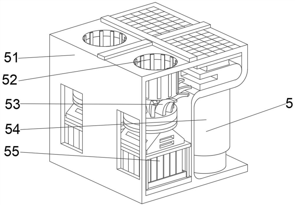
[0041] Wherein, the dedusting device 5 comprises a dedusting frame 51, the top left side of the dedusting frame 51 is provided with a dust collecting port 52, the two sides of the inner chamber bottom of the dedusti...

Embodiment 2

[0047] see Figure 1-6 , on the basis of Embodiment 1, the present invention provides a technical solution: a method for using mine wet dust removal, step 1: install the equipment, connect the adjustment member 4 with the circulation box 2, and connect the circulation box 2 Insert the middle part of the water storage tank 1, and fill the inside of the water storage tank 1 with water;

[0048] Step 2: When starting the equipment, connect the fan installed inside the dust removal frame 51 with the dust collection port 52, drive the dust to enter the inside of the filter mechanism 55 through the positioning of the support plate 53, connect the humidifying mechanism 54 with the filter mechanism 55, and carry out the rapid removal of dust clean up;

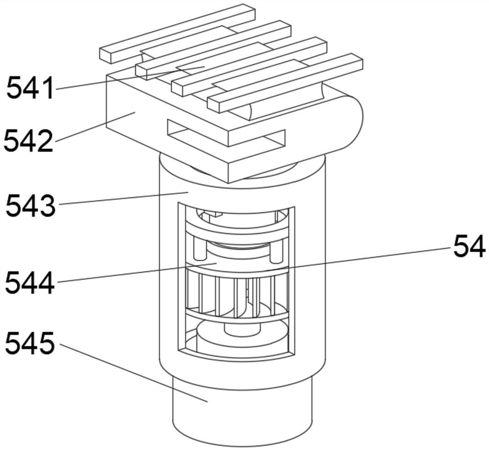
[0049] Step 3: Transport the internal water quantitatively to the interior of the humidifying cylinder 543 through the water blocking pipe 545, use the reinforcing body 544 to gather the water in the humidifying cylinder 543 driven by...


PUM


Abstract

The mining wet-type dust removal method comprises a water storage tank, the top of the outer wall of the left side of the water storage tank is fixedly connected with a circulation tank, a water outlet pipeline is arranged in the middle of the top of the outer wall of the left side of the circulation tank, the top end of the water outlet pipeline communicates with an adjusting part, and the outer wall of one side of the adjusting part is fixedly connected with a dust removal device. And the bottom of the dust removal device is fixedly connected with a water storage tank, and a control panel is fixedly connected to the middle of the outer wall of the left side of the dust removal device. According to the wet dust removal method for the mine, cyclic utilization of water flow is facilitated, waste of water resources is reduced, the treatment efficiency of dust is improved, separation of an internal space is facilitated, and the situation that the water flow permeates out or dust is accumulated in the interior and cannot be thoroughly cleaned is avoided; and therefore, the probability of secondary dust raising is reduced, gas exhausted from the interior is moist, and internal parts are convenient to maintain.

Description

technical field [0001] The invention relates to the technical field of dust removal equipment, in particular to a mine wet dust removal method. Background technique [0002] In the mining industry, preventing mine dust hazards, improving mine working conditions, and protecting the lives and health of miners is a very important task in the mining sector. With the development of the mining industry to large-scale, centralized and mechanized, the intensity of dust production continues to increase and the hazards become increasingly serious. , the requirements for dust prevention work are becoming increasingly strict and urgent. Coal and rocks are broken during excavation, forming a large amount of dust. Coal shearers and belt conveyors will also produce a large amount of dust at the coal drop, and the diffuse dust seriously threatens The health of coal miners is seriously affected, the incidence of pneumoconiosis is significantly higher than that of other industries, and the wo...

Claims


Application Information

Patent Timeline
Patent Type & Authority Applications(China)
IPC IPC(8): B01D50/60
Inventor 林宏
Owner 林宏
Why Eureka
Try Eureka