Heat dissipation structure

A technology of heat dissipation structure and heat dissipation holes, which is applied in the field of computer applications and can solve problems such as difficult removal of dust

Pending Publication Date: 2022-03-22
STATE GRID BEIJING ELECTRIC POWER +1
View PDF0 Cites 0 Cited by
  • Summary
  • Abstract
  • Description
  • Claims
  • Application Information

AI Technical Summary

Problems solved by technology

[0004] The main purpose of the present invention is to provide a heat dissipation structure to solve the problem in t

Method used


Image

  • Heat dissipation structure
  • Heat dissipation structure
  • Heat dissipation structure

Examples


Example Embodiment

[0046] Example 1

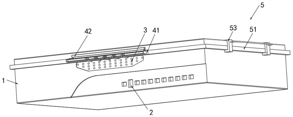
[0047] Computer network vulnerability investigation protection device, see Figures 1 to 7 The housing 1, the housing 1 is provided with an interface 2, and the upper side of the housing 1 is uniformly opened, and the front side of the housing 1 is provided with a drive assembly 4, a drive assembly. 4 The dust in the heat dissipating hole 3 is introduced through the own matching post 472, and both sides of the drive assembly 4 are in contact with the fixing assembly 5, and the fixing assembly 5 is in contact with the outer wall of the housing 1, and the fixing assembly 5 can assist the heat dissipation hole 3. Export the heat on the housing 1.

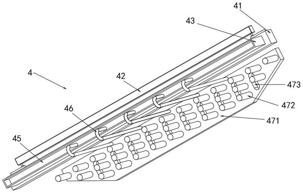
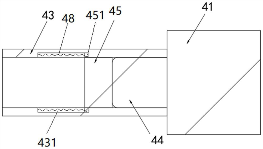
[0048] The drive assembly 4 includes a heat transfer rod 41 that is fixedly coupled to the front side of the housing 1, both of which are made by a copper aluminum alloy, and an electric heating device 42 is provided with an electric heating device 42 for The heating heat transfer rod 41, a temperature sensor can be provi...

Example Embodiment

[0054] Example 2

[0055] See figure 2 and Figure 5 Uniformly open a ventilation hole 473 on the connecting plate body 471, by providing a venting hole 473 mounted on the connecting plate body 471 without affecting the plate body 471, the hot air inside the housing 1 can pass The vent 473 flows to the heat dissipation hole 3 to facilitate increasing heat dissipation efficiency.

[0056] The remaining structures are the same as those in Example 1.

[0057] From the above description, it can be seen that the above embodiments of the present invention achieve the following technical effects:

[0058] The heat dissipation structure of the present invention includes a housing 1, a heat dissipating hole 3 is provided on the housing 1; the moving member 45, the moving member 45 is disposed outside the housing 1; the matching post 472, the matching post 472 is disposed inside the housing 1, The matching column 472 is used to insert in the heat dissipation hole 3 to clean the heat dissipat...


PUM


Abstract

The invention provides a heat dissipation structure, and the structure comprises a housing which is provided with heat dissipation holes. The moving part is arranged outside the shell; the matching columns are arranged in the shell, and the matching columns are used for being inserted into the heat dissipation holes so as to clean the heat dissipation holes; one end of the connecting frame is connected with the moving part, and the other end of the connecting frame is connected with the matching column; wherein the moving part and the matching column are both movably arranged, so that the matching column enters the heat dissipation holes by driving the moving part to move, and the heat dissipation structure solves the problem that dust in the heat dissipation holes in the vulnerability detection server in the prior art is difficult to remove.

Description

technical field [0001] The invention relates to the field of computer applications, in particular to a heat dissipation structure. Background technique [0002] With the continuous advancement of science and technology, the application of computer technology in daily life is more popular. While the development of computers brings convenience to people's lives, it also brings some information security risks to people. The network loopholes of computers have become a concern of people. An important issue of the Internet, some programs can destroy the network system, and can also lurk in the network and transmit user data through the network, thereby causing property losses. Therefore, it is necessary to discover network security vulnerabilities in time by deploying a vulnerability detection server. [0003] At present, cooling holes are usually set up on the vulnerability detection server to ensure heat dissipation, but dust easily enters the cooling holes, and it is difficul...

Claims


Application Information

Patent Timeline
IPC IPC(8): G06F1/18G06F1/20
CPCG06F1/181G06F1/20G06F2200/1638
Inventor 王超王小虎任天宇董佳涵郭广鑫李博文师恩洁
Owner STATE GRID BEIJING ELECTRIC POWER
Why Eureka
Try Eureka