Centrifugal clutch assembly integrated structure and automatic speed change hub with large speed change ratio

A technology of centrifugal clutch and automatic transmission, which is applied in the direction of vehicle gearboxes, vehicle components, wheel transmissions, etc., can solve problems such as the need to improve the riding experience, affect reliability, and complex assembly, so as to optimize the riding experience and prolong the life of the vehicle. Effects of service life, reduced number of parts and assembly process

Pending Publication Date: 2022-03-25
BAFANG ELECTRIC (SUZHOU) CO LTD
View PDF2 Cites 0 Cited by
  • Summary
  • Abstract
  • Description
  • Claims
  • Application Information

AI Technical Summary

Problems solved by technology

[0005] However, the transmission mechanism in the above-mentioned patent has only two gears, and the riding experience needs to be improved after being installed on the vehicle.
While increasing the gears of the transmission mechanism, it is also necessary to consider the complex assembly caused by the large number of parts, the high cost and the impact on reliability, as well as how to increase the transmission ratio.

Method used


Image

  • Centrifugal clutch assembly integrated structure and automatic speed change hub with large speed change ratio
  • Centrifugal clutch assembly integrated structure and automatic speed change hub with large speed change ratio
  • Centrifugal clutch assembly integrated structure and automatic speed change hub with large speed change ratio

Examples


Embodiment 1

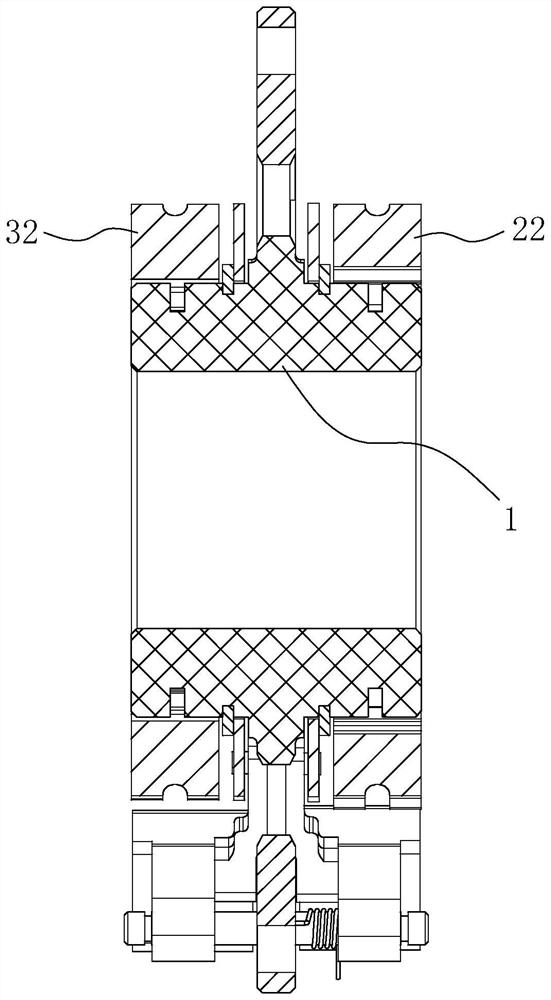
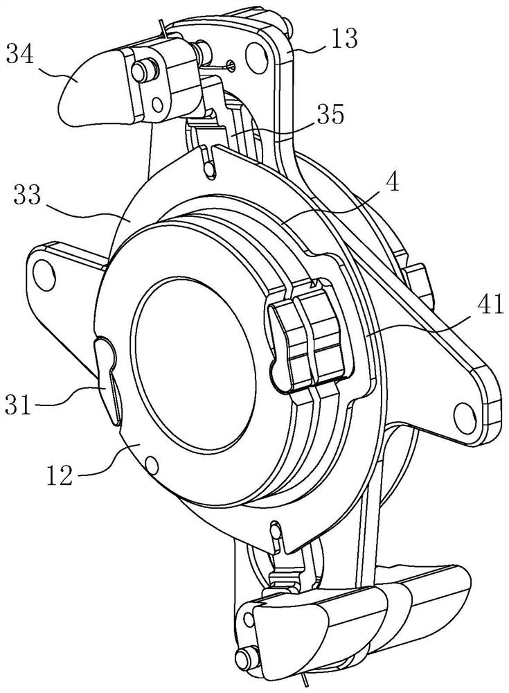
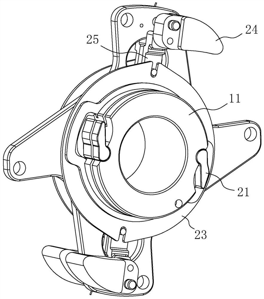
[0040] An integrated structure of centrifugal clutch components, refer to Figure 1 to Figure 3 , which includes the first clutch inner ring part 11, the first clutch driver 21 and the first buffer frame 22, and the second clutch inner ring part 12, the second clutch driver 31 and the second buffer frame 32; the first clutch inner The ring part 11 and the second clutch inner ring part 12 are fixedly connected or integrally formed to form an integrated inner ring 1; preferably, in this embodiment, the integrated inner ring 1 is integrally formed, so that the number of parts and the assembly process can be reduced, and the production cost and detection cost, and can improve the reliability and stability of the work, and can also simplify the structure and optimize the size, such as reducing the axial size; of course, in other optional embodiments, the first clutch inner ring part 11 and the second clutch inner ring part 12 can also be fixedly connected as a whole by means of wel...

Embodiment 2

[0044] An automatic transmission hub with a large transmission ratio, refer to Figure 1 to Figure 5 , including a hub tube 8, the hub tube 8 is respectively provided with the first planetary gear assembly, the second planetary gear assembly and the integrated structure of the centrifugal clutch assembly in Embodiment 1, and the integrated structure of the centrifugal clutch assembly is located between the first planetary gear assembly and the second planetary gear assembly Between the two planetary gear assemblies; the fixing plate 13 is pierced with fasteners connected to the inner end surface of the hub tube 8; in this embodiment, two sets of planetary gear assemblies are set to form three gears, and according to the speed of the power output unit To realize the automatic switching of the three gears, which can further improve the riding experience.

[0045] refer to Figure 1 to Figure 5 Specifically, in this embodiment, the first planetary gear assembly includes a first ...


PUM


Abstract

The invention discloses a centrifugal clutch assembly integrated structure and an automatic speed change hub with a large gear ratio, and relates to the field of speed change devices. According to the technical scheme, the clutch is characterized by comprising a first clutch inner ring part, a first clutch driving piece and a first buffer frame; and a second clutch inner ring portion, a second clutch driving member and a second buffer rack. The first clutch inner ring part and the second clutch inner ring part are fixedly connected or integrally formed to form an integrated inner ring. According to the invention, the number of parts and assembly procedures can be reduced, the production cost and the detection cost can be reduced, the reliability and the stability can be improved, meanwhile, the structure can be simplified, the size can be optimized, automatic switching of three gears can be realized by utilizing the output speed, and the gear ratio can be improved, so that the riding experience can be further optimized.

Description

technical field [0001] The invention relates to the field of transmission devices, more specifically, it relates to an integrated structure of a centrifugal clutch assembly and an automatic transmission hub with a large transmission ratio. Background technique [0002] The general internal speed change mechanism uses centrifugal force to realize automatic speed change. When a certain cadence speed is reached, the centrifugal block is thrown away to realize automatic upshifting. When the cadence speed drops below the speed change point, the centrifugal block will shrink to realize automatic downshifting. For example, it is shown in the Chinese patent whose authorized announcement number is CN208882034U. [0003] However, for the vehicle using the above-mentioned speed change mechanism, when the vehicle is running at high speed (greater than the speed change point), if the rider does not want to step on it, or does not need to step on the downhill, the speed change mechanism w...

Claims


Application Information

Patent Timeline
Patent Type & Authority Applications(China)
IPC IPC(8): B62M11/16B62M11/18
CPCB62M11/16B62M11/18
Inventor 邹斌黄善劲
Owner BAFANG ELECTRIC (SUZHOU) CO LTD
Why Eureka
Try Eureka