Subpackaging device for rare earth inspection
A sub-packaging and rare earth technology, applied in packaging, transportation and packaging, packaging item types, etc., can solve the problems of cumbersome operation, low sub-packaging efficiency, time-consuming and energy-consuming, etc., to achieve simple operation and improve sub-packaging efficiency , the effect of preventing self-shaking
- Summary
- Abstract
- Description
- Claims
- Application Information
AI Technical Summary
Problems solved by technology
Method used
Image
Examples
Embodiment 1
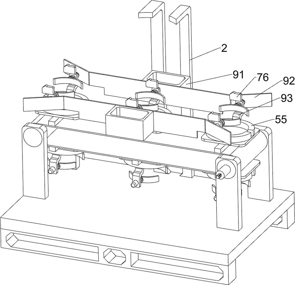
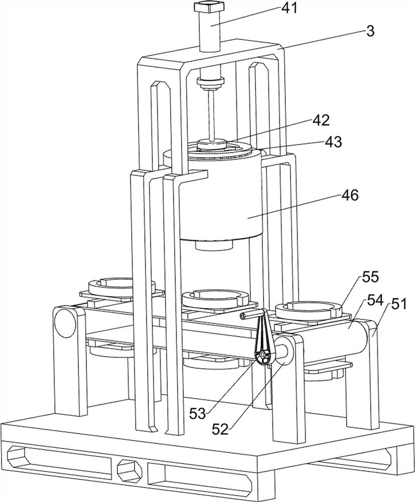
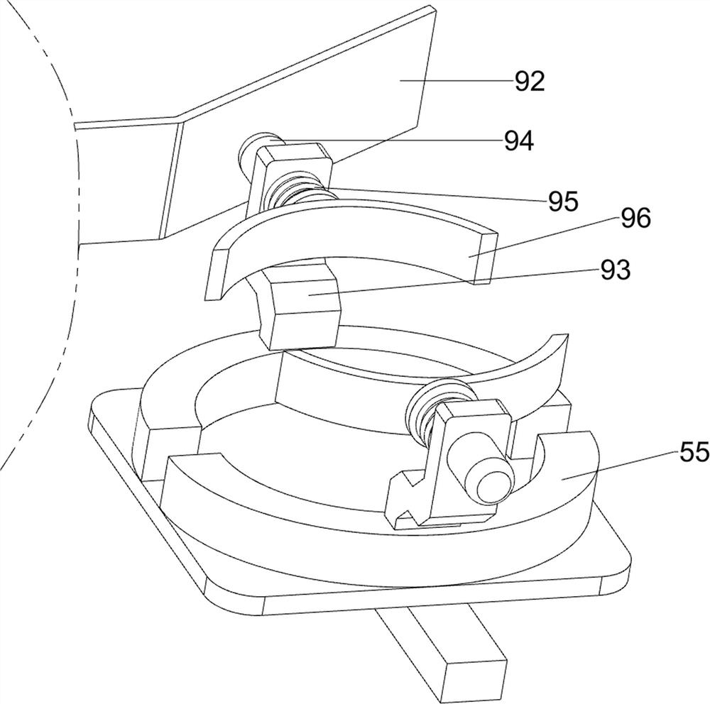
[0030] A kind of sub-packaging device for rare earth inspection, such as Figure 1-3 As shown, it includes a base 1, a frame 2, a bracket 3, a feeding mechanism 4 and a transport assembly 5, the front and rear sides of the top of the base 1 are connected with a frame 2, and the tops of the two frames 2 are connected with a bracket 3. A blanking mechanism 4 is provided between the frame 2 and the bracket 3, and a transport component 5 is provided on the top of the base 1.
[0031] Blanking mechanism 4 comprises cylinder 41, rotating disk 42, pressure plate 43, slide block 44, stirring bar 45 and charging barrel 46, and cylinder 41 is installed on the support 3, is connected with rotating disk 42 on the telescoping rod of cylinder 41, and rotating disk The bottom of 42 is connected with a pressure plate 43, the outer wall of the pressure plate 43 is connected with a slide block 44, the bottom of the pressure plate 43 is connected with a plurality of stirring rods 45, and the inn...
Embodiment 2
[0035] On the basis of Example 1, such as figure 1 , image 3 and Figure 4 As shown, it also includes a discharge mechanism 6. The discharge mechanism 6 includes a first fixed block 61, a rotating rod 62, a torsion spring 63 and a baffle plate 64, and the front and rear sides of the bottom of the charging barrel 46 are connected with first fixed blocks. Block 61, on the first fixed block 61, the rotating type is connected with rotating rod 62, is connected with torsion spring 63 between rotating rod 62 and the first fixed block 61, is connected with baffle plate 64 on the rotating rod 62, and baffle plate 64 and charging Barrel 46 fits.
[0036] Initially, the baffle plate 64 blocks the charging barrel 46, so that the rare earth in the charging barrel 46 can be prevented from falling on the flat belt 54, thereby preventing the waste of rare earth. Finally, the baffle plate 64 can be rotated and opened manually, the rotating rod 62 rotates thereupon, the torsion spring 63 i...
Embodiment 3
[0038] On the basis of Example 2, such as figure 1 and Figure 5As shown, a driving mechanism 8 is also included, and the driving mechanism 8 includes a servo motor 81, a second fixed frame 82, a missing gear 83 and a second gear 84, a servo motor 81 is installed on the right front side of the top of the base 1, and the right front side of the top of the base 1 A second fixed mount 82 is connected, and the second fixed mount 82 is positioned at the rear of the servo motor 81. The second fixed mount 82 is rotatably connected with a missing gear 83. The missing gear 83 is connected with the servo motor 81, and the right pulley 52 is connected to the front. There is a second gear 84 which meshes with the missing gear 83 .
[0039] The servo motor 81 can be started to rotate the missing gear 83, and the missing gear 83 can rotate the right side pulley 52 intermittently through the second gear 84, so that there is no need to manually turn the handle 53; in this way, the driving me...
PUM
 Abstract
Description
Claims
Application Information
 - R&D
- Intellectual Property
- Life Sciences
- Materials
- Tech Scout
- Unparalleled Data Quality
- Higher Quality Content
- 60% Fewer Hallucinations
Browse by: Latest US Patents, China's latest patents, Technical Efficacy Thesaurus, Application Domain, Technology Topic, Popular Technical Reports.
© 2025 PatSnap. All rights reserved.Legal|Privacy policy|Modern Slavery Act Transparency Statement|Sitemap|About US| Contact US: help@patsnap.com


