
Light guide optical system capable of saving space and achieving uniform lighting and automobile signal lamp thereof

A space-saving, optical system technology, applied to optical signals, light guides of lighting systems, optics, etc., can solve the problems of cost and light efficiency reduction, high space requirements, etc., to achieve good lighting uniformity, uniform lighting effect, and added diffusion effect of effect

Pending Publication Date: 2022-03-25
MAGNETI MARELLI AUTOMOTIVE COMPONENTS WUHU
View PDF2 Cites 1 Cited by
  • Summary
  • Abstract
  • Description
  • Claims
  • Application Information

AI Technical Summary

Problems solved by technology

[0003] In the existing optical system of light guide and inner lens, light guide teeth are made on the back of the light guide. The light emitted from the light guide is emitted to the front of the car lamp, and then irradiated on the inner lens. It is necessary for the light guide to have a larger light mixing distance from the inner lens. , that is, a relatively large distance is required between the light output surface and the light incident surface of the inner lens to achieve a relatively uniform lighting effect, but this will lead to high space requirements, facing the development trend of car lights that are becoming narrower and smaller spaces. It will be a very difficult problem. At the same time, if the spatial distance cannot meet the uniformity of optical lighting, it will be a major defect. OEMs and car buyers have higher and higher requirements for light efficiency and uniformity, and this problem is becoming more and more difficult.
In addition, for the light guide plus inner mirror system, if the light guide is installed in the positive direction, the effective optical path from the light guide to the inner mirror will be shorter due to space constraints, and the problems of uniformity and bright spots will be more difficult to solve. The existing technology will use the inner mirror material Emulsified materials, or intraocular lens texture treatment to improve uniformity, but this will bring problems of cost and light efficiency reduction

Method used


Image

  • Light guide optical system capable of saving space and achieving uniform lighting and automobile signal lamp thereof
  • Light guide optical system capable of saving space and achieving uniform lighting and automobile signal lamp thereof
  • Light guide optical system capable of saving space and achieving uniform lighting and automobile signal lamp thereof

Examples


Embodiment 1

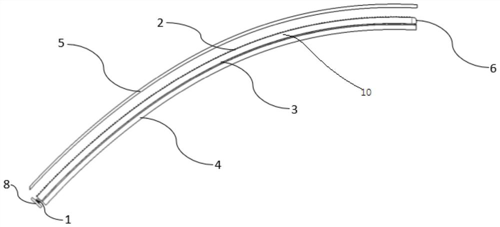
[0044] Such as figure 1 Shown is a structural schematic of a light guide optical system that saves space and achieves uniform lighting Figure 1 ,Such as figure 2 Shown is a structural schematic of a light guide optical system that saves space and achieves uniform lighting Figure II ,Such as image 3 Shown is a top-view diagram of a light guide optical system that saves space and achieves uniform lighting, such as Figure 4 Shown is a schematic top view of a light guide optical system that saves space and achieves uniform lighting, such as Figure 5 Shown is a partial enlargement of the space-saving light guide optics for uniform lighting Figure 1 ,Such as Image 6 Shown is a partial enlargement of the space-saving light guide optics for uniform lighting Figure II, including a light source 1, the light source 1 is fixedly arranged on a circuit board 8, and in this embodiment, the circuit board 8 is arranged on a PCB board. The light source 1 is correspondingly arran...

Embodiment 2

[0050] Embodiment 2 is formed on the basis of Embodiment 1, and the pattern opening direction of the second diffuse optical pattern 9 and the pattern opening direction of the light guide total reflection optical teeth 2 are arranged perpendicular to each other. The second diffusing optical pattern 9 can diffuse the outgoing light in the up and down direction, which can not only expand the lighting area, but also eliminate bright spots, so that the lighting uniformity is better.

Embodiment 3

[0052] Embodiment 3 is formed on the basis of Embodiment 1. The pattern opening direction of the first diffuse optical pattern 7 and the pattern opening direction of the light guide total reflection optical teeth 2 are arranged perpendicular to each other to improve uniformity.

[0053] Working principle: as Figure 7 Shown is a schematic of the optical path of the space-saving light guide optical system for uniform lighting Figure 1 ,Such as Figure 8 Shown is a schematic of the optical path of the space-saving light guide optical system for uniform lighting Figure II , the light guide total reflection optical tooth 2 is arranged on the side of the light guide 10 away from the upper surface of the light guide bracket 4, for this optical system, the effective optical path in the optical design is the distance between the light export light surface and the inner lens light incident surface, which is Figure 8 Middle distance b1+b2. Such as Figure 16 Shown is a schematic...


PUM


Abstract

The invention provides a light guide optical system capable of saving space and achieving uniform lighting and an automobile signal lamp thereof in the technical field of automobile lamps. The light guide optical system comprises a light source, and the light source is correspondingly arranged at the end of a light guide body; an inner lens is correspondingly arranged above the light conductor, and a light guide bracket is correspondingly arranged below the light conductor; the light guide body comprises light guide total reflection optical teeth and a light guide modeling total reflection surface, the light guide total reflection optical teeth are arranged on the light guide body, and the light guide total reflection optical teeth are arranged corresponding to the light incident surface of the inner lens; the light guide support is provided with a first diffusion optical pattern, and the first diffusion optical pattern is arranged corresponding to the light guide modeling total reflection surface. The problem that the lighting effect is not uniform due to the fact that the photoconductor is too close to the inner lens is solved, the effect of increasing the light mixing distance in a small space is achieved, meanwhile, the diffusion effect is added, and the uniform lighting effect is achieved.

Description

technical field [0001] The invention relates to the technical field of vehicle lamps, in particular to a space-saving light guide optical system and a vehicle signal lamp for achieving uniform lighting. Background technique [0002] There are many ways to light up the car's turn signals, tail lights and other lighting units. Compared with traditional reflector lights, the use of light guide technology can improve the uniformity of light distribution and reduce the phenomenon of dark areas. The light guide solution in the prior art is to use the light guide teeth on the back of the light guide to reflect light to the total reflection surface of the light guide shape and then emit. It has no optical diffusion pattern and no optical diffusion effect. [0003] In the existing optical system of light guide and inner lens, light guide teeth are made on the back of the light guide. The light emitted from the light guide is emitted to the front of the car lamp, and then irradiated ...

Claims


Application Information

Patent Timeline
Patent Type & Authority Applications(China)
IPC IPC(8): F21S43/235F21S43/20F21S43/27F21S43/33F21V5/04F21V8/00F21V17/10F21V5/00F21V7/00F21V7/28F21V7/24F21W103/20
CPCF21S43/235F21S43/20F21S43/27F21S43/33F21V5/04F21V17/10F21V5/002F21V7/0091F21V7/28F21V7/24F21V2200/00F21W2103/20
Inventor 江璐芸
Owner MAGNETI MARELLI AUTOMOTIVE COMPONENTS WUHU
Learn More