Testing device for X-ray CT image cross-sectional matching and cross-sectional matching method

A technology of testing devices and matching methods, which is applied in the direction of measuring devices, instruments, scientific instruments, etc., and can solve problems such as interference and maintaining consistent fault matching

Pending Publication Date: 2022-03-25
北京路生工程技术有限公司 +2
View PDF0 Cites 0 Cited by
  • Summary
  • Abstract
  • Description
  • Claims
  • Application Information

AI Technical Summary

Problems solved by technology

[0005] In view of the problem that in the existing X-rayCT image tomographic matching method, because the state of the specimen cannot be kept consistent in multiple scans, it will interfere with the tomographic matching. The present invention provides a test device for X-rayCT image tomographic matching and a tomographic matching method

Method used


Image

  • Testing device for X-ray CT image cross-sectional matching and cross-sectional matching method
  • Testing device for X-ray CT image cross-sectional matching and cross-sectional matching method
  • Testing device for X-ray CT image cross-sectional matching and cross-sectional matching method

Examples


specific Embodiment approach 1

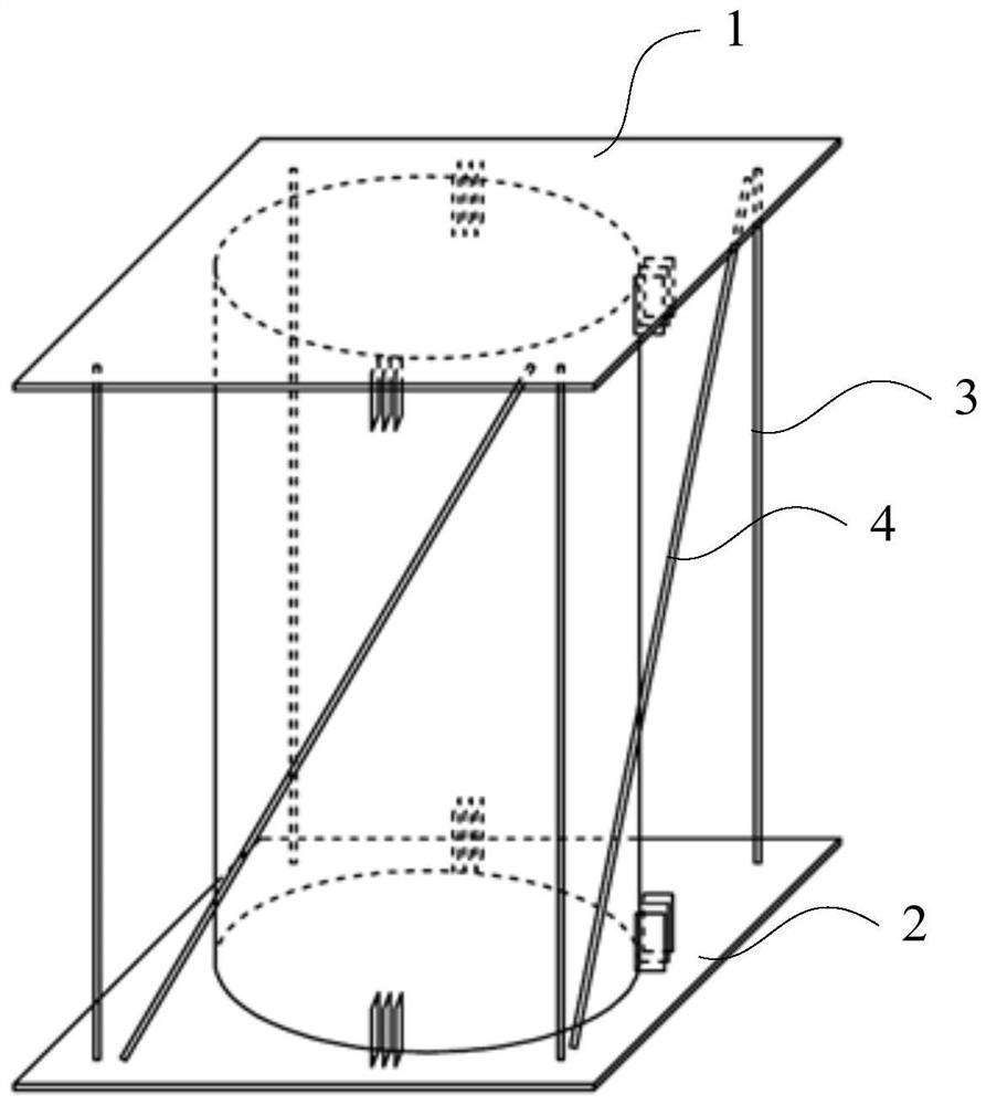
[0043] Specific implementation mode 1. Combination Figure 1 to Figure 3 As shown, the first aspect of the present invention provides a test device for tomographic matching of X-rayCT images, including an upper end plate 1, a lower end plate 2, four vertical support rods 3 and two oblique marker rods 4,

[0044] Four vertical support rods 3 are evenly arranged and supported between the upper end plate 1 and the lower end plate 2, the inner space formed by the upper end plate 1, the lower end plate 2 and the four vertical support rods 3 is used for installing the scanning specimen, scanning test piece Azimuths are fixed between the upper end plate 1 and the lower end plate 2 through the fixing parts respectively;

[0045]Among the three adjacent vertical support rods 3 , an oblique marking rod 4 is arranged between every two adjacent vertical supporting rods 3 , and the inclinations of the two oblique marking rods 4 are the same.

[0046] In this embodiment, the vertical suppo...

specific Embodiment approach 2

[0055] Specific embodiment two, combine Figure 1 to Figure 4 As shown, another aspect of the present invention also provides an X-rayCT image tomographic matching method, which is implemented based on the test device for X-rayCT image tomographic matching described in the first specific embodiment, including:

[0056] First, install the scanning specimen in the initial state in the test device, perform a reference tomographic scan, and obtain a reference tomographic image;

[0057] Then, take out the scanned specimen in the initial state for damage test;

[0058] Installing the scanned specimen after the damage test in the test device, performing a post-damage tomographic scan, and obtaining a post-damage tomographic image;

[0059] In the reference tomographic image, through the distance between each oblique marking rod 4 and two adjacent vertical support rods 3, calculate the reference height mark value of the reference tomographic image at the height position of the scann...

specific Embodiment

[0091] combine Figure 1 to Figure 4 , taking the tomographic image matching before and after freeze-thaw damage of asphalt mixture as an example, the specific implementation of the present invention is described in detail:

[0092] Step 1: Bonding of the fixed clip:

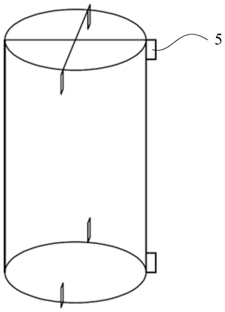
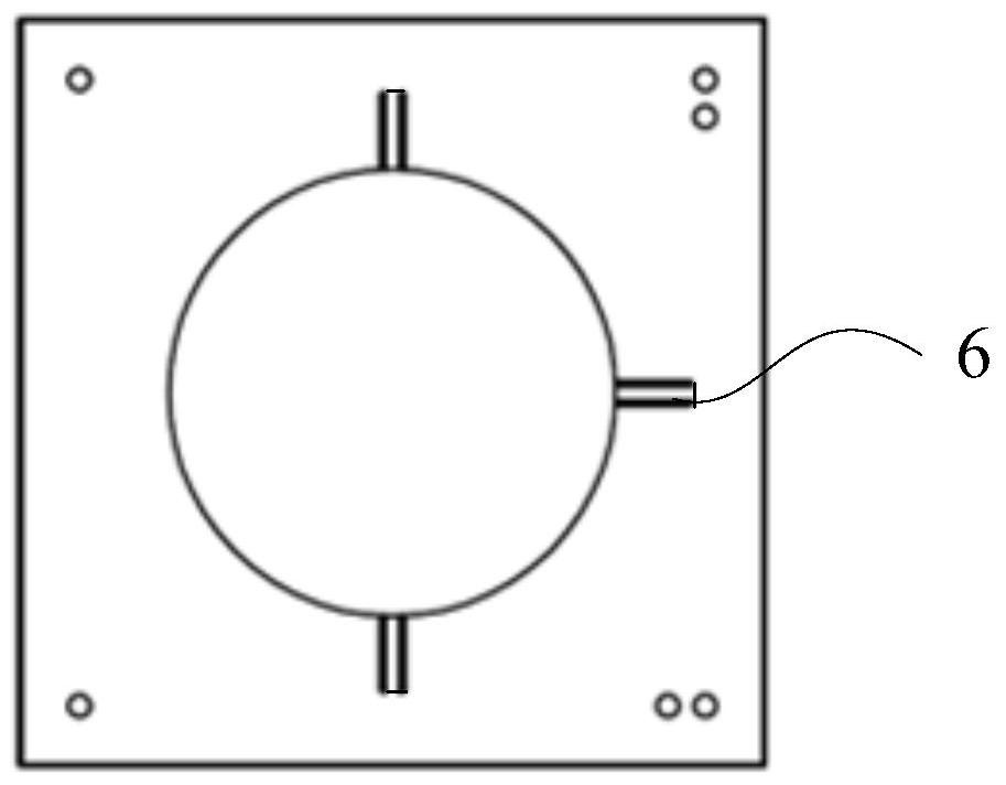
[0093] On the cylindrical asphalt mixture specimen, mark the cross line of the specimen through the center of the circle to determine the quartile position of the side wall of the specimen, see appendix figure 2 As shown: AB glue is used to bond the metal fixing clips and fix them on the side wall of the quarter position. A total of 6 fixing clips are bonded, and the upper and lower positions correspond to each other. After the AB glue is solidified, install the upper and lower end plates of the fixture on the upper and lower bottom surfaces of the specimen, and test whether the position of the fixing clip is appropriate. If the fixing clip cannot be placed in the clip groove, it needs to be bonded again until...


PUM

PropertyMeasurementUnit
thicknessaaaaaaaaaa
widthaaaaaaaaaa

Abstract

The invention discloses a testing device for X-ray CT image cross-sectional matching and a cross-sectional matching method, and belongs to the technical field of material microstructure monitoring. The invention aims to solve the problem that in an existing X-ray CT image cross-sectional matching method, the cross-sectional matching is interfered due to the fact that the state of a test piece cannot be kept consistent in multiple times of scanning. The device comprises an upper end plate, a lower end plate, four vertical supporting rods and two oblique marking rods, the four vertical supporting rods are evenly arranged and supported between the upper end plate and the lower end plate, and an internal space formed by the upper end plate, the lower end plate and the four vertical supporting rods is used for installing a scanning test piece; the scanning test piece and the upper end plate as well as the scanning test piece and the lower end plate are fixed through fixing pieces; in the three adjacent vertical supporting rods, one oblique marking rod is arranged between every two adjacent vertical supporting rods, and the inclination degrees of the two oblique marking rods are the same. The method is used for image cross-sectional matching.

Description

technical field [0001] The invention relates to a testing device and a tomographic matching method for X-rayCT image tomography matching, and belongs to the technical field of material mesoscopic structure monitoring. Background technique [0002] Industrial CT technology is a non-destructive testing technology commonly used in the field of civil engineering materials research at this stage, which can realize high-precision detection of the internal structure of materials, damage cracks, and pore distribution. Using this technology to compare and analyze X-rayCT tomographic images before and after the damage test, and then study the characteristics of crack development, fatigue / freeze-thaw damage, medium diffusion / crystallization, and pore blockage / deformation of civil engineering materials, is the current field of research. research hotspots. Among them, the accurate judgment and acquisition of the X-ray CT images of the same section before and after the specimen damage is...

Claims


Application Information

Patent Timeline
Patent Type & Authority Applications(China)
IPC IPC(8): G01N23/046
CPCG01N23/046
Inventor 刘福军徐慧宁石浩李恒祯栗诗源张子寒秦智强周宇余宏伟郑直冷滨滨张伟建
Owner 北京路生工程技术有限公司
Why Eureka
Try Eureka