Optical system and head-mounted display device

A technology for optical systems and display devices, applied in optics, optical components, instruments, etc., can solve the problems of ghosting, low light efficiency, and high production costs, achieve strong convergence ability, reduce stray light, and achieve the effect of miniaturization

Active Publication Date: 2022-03-25
GOERTEK OPTICAL TECH CO LTD
View PDF9 Cites 2 Cited by
  • Summary
  • Abstract
  • Description
  • Claims
  • Application Information

AI Technical Summary

Problems solved by technology

In current VR devices, if a 1.4-inch display screen achieves a large field of view (FOV) and a short total optical length (TTL), the conventional optical solution is a folded optical path structure, but it has high production costs and low light efficiency. (<25%) and there are problems with ghosting

Method used


Image

  • Optical system and head-mounted display device
  • Optical system and head-mounted display device
  • Optical system and head-mounted display device

Examples


Embodiment 1

[0130] Embodiment 1 provides an optical system, and Table 1 is used to show the structural parameters in the optical system.

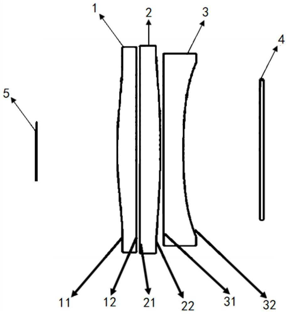
[0131] Table 1 lists the optical surface number (Surface) numbered sequentially from the human eye 5 (diaphragm) to the display screen 4, the curvature (C) of each optical surface on the optical axis, and the number of optical surfaces from the human eye 5 (diaphragm) The distance (T) between each optical surface and the next optical surface on the optical axis of the display screen 4, and the even-order aspheric coefficient α 2 、α 3 、α 4 .

[0132] Among them, the aspheric coefficient can satisfy the following equation:

[0133]

[0134] In formula (1): z is the coordinate along the optical axis, Y is the radial coordinate in units of lens length, C is the curvature (1 / R), K is the cone coefficient (Coin Constant), and αi is the height The coefficient of the second term, 2i is the order of Aspherical Coefficient (the order of Aspherical Coeffic...

Embodiment 2

[0143] Embodiment 2 provides an optical system, and Table 2 is used to show the structural parameters in the optical system.

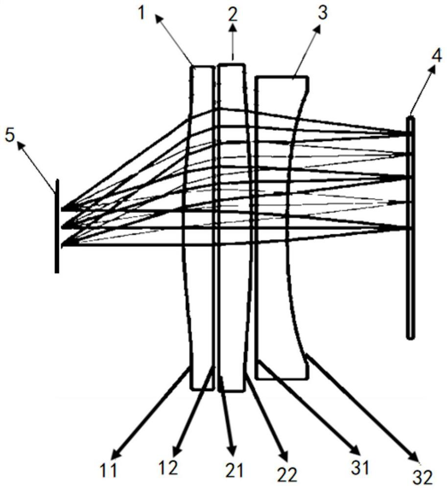
[0144] The optical system can be as Figure 6 shown.

[0145] Table 2 lists the optical surface number (Surface) numbered sequentially from the human eye 5 (diaphragm) to the display screen 1, the curvature (C) of each optical surface on the optical axis, and the number of optical surfaces from the human eye 5 (diaphragm) The distance (T) between each optical surface and the next optical surface on the optical axis of the display screen 1, and the even-order aspheric coefficient α 2 、α 3 、α 4 .

[0146] Table 2

[0147]

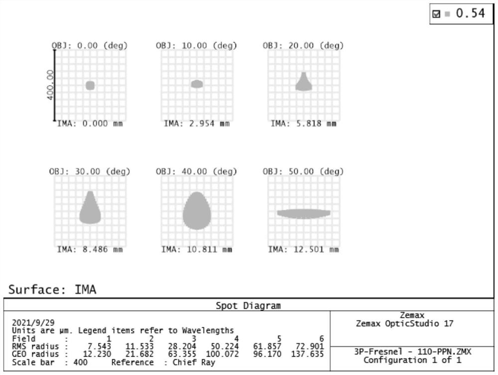
[0148] The performance of the optical system of embodiment 2 is reflected by the following parameters:

[0149] Such as Figure 7 As shown, the maximum spot size is the maximum field of view 1.0F, and its maximum value is less than 80μm.

[0150] Such as Figure 8 As shown, the RGB wavelengths of field curvature in the T&S...


PUM

PropertyMeasurementUnit
thicknessaaaaaaaaaa
thicknessaaaaaaaaaa

Abstract

The embodiment of the invention discloses an optical system and head-mounted display equipment. The optical system comprises a third lens, a second lens and a first lens which are sequentially arranged in the propagation direction of incident light. Three Fresnel surfaces are arranged in the optical system, and two Fresnel surfaces are arranged adjacently; the focal power of the third lens is positive; the field angle of the optical system is larger than or equal to 100 degrees. The embodiment of the invention provides an optical structure design scheme with short focus, high luminous efficiency and large FOV. The optical system provided by the embodiment of the invention can be applied to head-mounted display equipment and the like.

Description

technical field [0001] The present application relates to the technical field of optical imaging, and more specifically, the present application relates to an optical system and a head-mounted display device. Background technique [0002] In recent years, augmented reality (Augmented Reality, AR) technology and virtual reality (Virtual Reality, VR) technology have been applied in smart wearable devices and developed rapidly. The core components of augmented reality technology and virtual reality technology are both display optical systems. Therefore, the quality of the display optical system will directly determine the quality of smart wearable devices. [0003] In the existing related technologies, a VR device is taken as an example. In current VR devices, if a 1.4-inch display screen achieves a large field of view (FOV) and a short total optical length (TTL), the conventional optical solution is a folded optical path structure, but it has high production costs and low li...

Claims


Application Information

Patent Timeline
Patent Type & Authority Applications(China)
IPC IPC(8): G02B27/01
CPCG02B27/0172G02B9/12G02B3/08G02B2027/0118G02B13/004G02B1/041G02B2027/0178
Inventor 孙琦赵博刚
Owner GOERTEK OPTICAL TECH CO LTD
Why Eureka
Try Eureka