Dustproof heat dissipation device for UV LED power supply

A heat dissipation device and power supply technology, applied in the direction of measuring devices, data processing power supply, digital processing power distribution, etc., can solve the problems of insufficient heat dissipation, reduced heat dissipation performance, short circuit or damage of electronic components, etc., to achieve fast installation and cleaning , Satisfy the protective ability and improve the effect of dustproof ability

Pending Publication Date: 2022-03-25
SHENZHEN GARLE ELECTRIC TECH CO LTD
View PDF5 Cites 0 Cited by
  • Summary
  • Abstract
  • Description
  • Claims
  • Application Information

AI Technical Summary

Problems solved by technology

[0003] 1. Set the heat dissipation holes to dissipate the heat inside the chassis through the heat dissipation holes. This natural way of heat dissipation brings out less heat. It does not meet the heat dissipation requirements on high-power UV LED power supplies, and the scope of application is small;
[0004] 2. There are cooling holes on the case shell, which can help to dissipate heat, but it is also the channel for external dust and humid air to enter the inside of the case; external dust enters the case and deposits on the electronic components, reducing its heat dissipation performance and causing electronic components to be damaged. In addition, in a humid air environment, air containing moisture enters the interior of the device, which can easily cause short circuits or damage to electronic components, greatly shortening the service life of electronic products

Method used


Image

  • Dustproof heat dissipation device for UV LED power supply
  • Dustproof heat dissipation device for UV LED power supply
  • Dustproof heat dissipation device for UV LED power supply

Examples


Embodiment

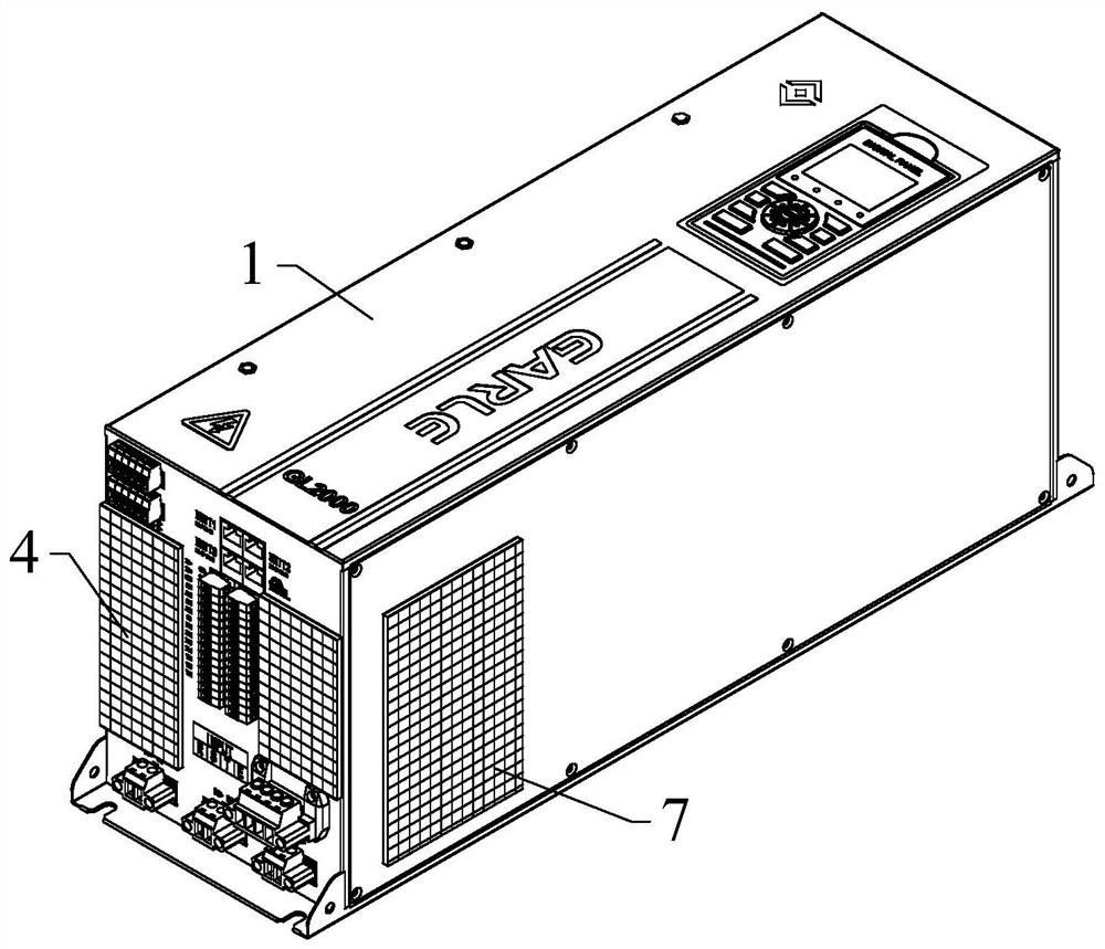
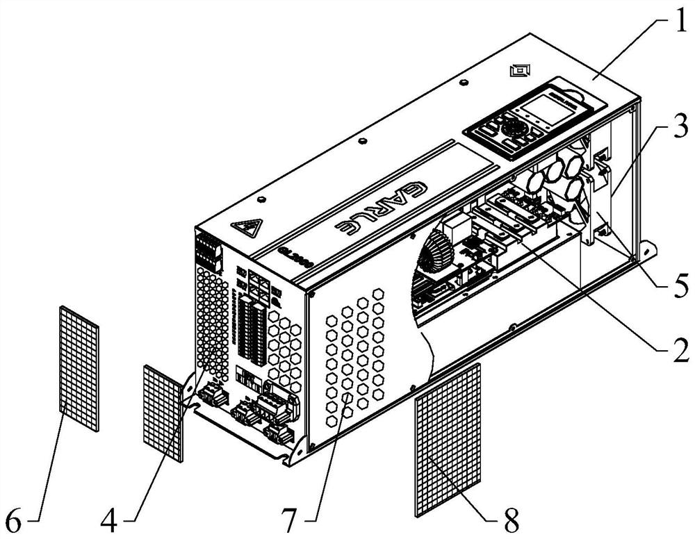
[0023] See Figure 1 to 3 As shown in the figure, the present invention provides a dust-proof heat dissipation apparatus for the UV LED power source, including the chassis housing 1, and the inside of the chassis casing 1 is provided with an electronic component 2, and the right end of the chassis housing 1 is provided. The wind hole 3, the left end of the chassis casing 1 is provided with a first inlet air hole 3, and the first inlet air hole 4 is formed into a heat dissipation airway, and the heat dissipation wind is independent cooling. The road is convenient for air to circulate in the chassis housing 1, and the inside of the chassis housing 1 will cool heat.

[0024] The inner side of the outlet 3 is provided with a heat dissipation fan 5, and the heat dissipation fan 5 is exhausted inside the chassis housing 1, and the heat of the electronic component 2 can be used according to different power, and the fan of different air volume is replaced, and the heat dissipation of diffe...


PUM


Abstract

The invention discloses a dustproof heat dissipation device for a UV LED power supply, and the device comprises a case housing, the interior of the case housing is provided with an electronic element, the right end of the case housing is provided with an air outlet hole, the left end of the case housing is provided with a first air inlet hole, and the air outlet hole, the first air inlet hole and the inner cavity of the case housing form a heat dissipation air channel. A cooling fan is arranged on the inner side of the air outlet hole, and a first dustproof mechanism is arranged on the outer side of the first air inlet hole. The first dustproof mechanism comprises a dustproof net and a soft magnetic strip, one side of the soft magnetic strip is provided with gum connected with the dustproof net, the other side of the soft magnetic strip is connected with the case shell in an adsorption mode, and the size of the dustproof net is matched with the size of the first air inlet hole. The dustproof heat dissipation device for the UV LED power supply, which adopts the structure, is good in heat dissipation effect and has relatively high dustproof and moistureproof capabilities.

Description

Technical field [0001] The present invention relates to the technical field of UV LED power supply devices, and in particular, to a dust-proof heat dissipation device for a UV LED power source. Background technique [0002] Usually, there is a large number of electronic components inside the UV LED power supply, which will generate heat during power-on, and when the UV LED power supply is working for a long time, the temperature of the fuselage will increase, thereby affecting electronics Performance; in order to facilitate the release of heat generated during operation within the UV LED power chassis, the existing technique is typically disposed on the chassis of the UV LED power supply, that is, on the left and right side panels or back panels of the housing. The grid or circular hole is to be exchanged between the inside of the chassis and the outside air, so that the heat inside the chassis is radiated through the heat dissipation hole, reducing the effect of reducing the int...

Claims


Application Information

Patent Timeline
Patent Type & Authority Applications(China)
IPC IPC(8): G06F1/26G06F1/20G06F1/18B01D46/12
CPCG06F1/26G06F1/20G06F1/181B01D46/12
Inventor 姜海峰李欢
Owner SHENZHEN GARLE ELECTRIC TECH CO LTD
Why Eureka
Try Eureka