
Digital grid method and terminal

A grid and digital technology, which is applied in the digital grid method and terminal field, can solve the problems of inability to reach and eliminate scattered rays, and achieve effective and thorough effects of eliminating the influence of scattering and suppressing the influence of scattering

Pending Publication Date: 2022-03-25
安健科技(重庆)有限公司
View PDF0 Cites 0 Cited by
  • Summary
  • Abstract
  • Description
  • Claims
  • Application Information

AI Technical Summary

Problems solved by technology

At present, there are also related digital grid image processing methods, but most of them only calculate the relevant information based on the captured images, and cannot completely eliminate the effect of scattered rays.

Method used


Image

  • Digital grid method and terminal
  • Digital grid method and terminal
  • Digital grid method and terminal

Examples


Embodiment 1

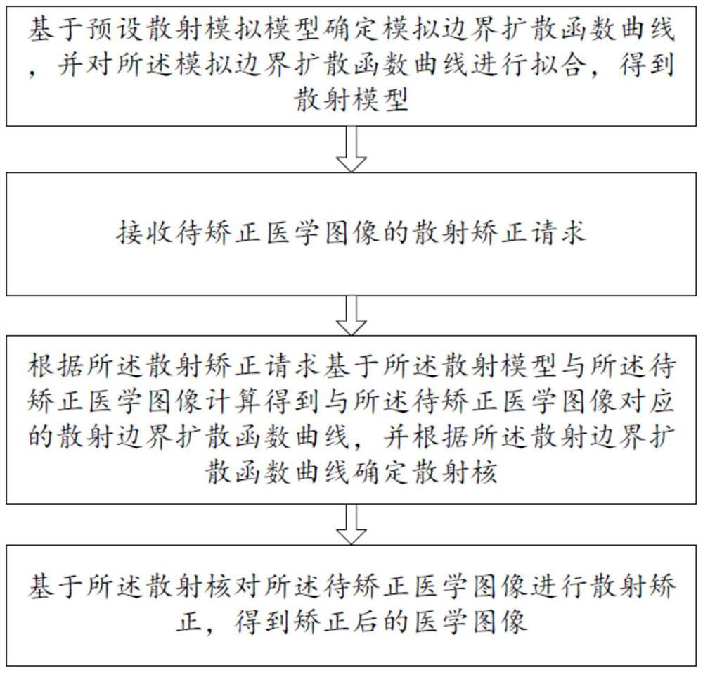
[0090] Please refer to figure 1 , 2 -8, a digital grid method of the present embodiment, comprising:

[0091] S1. Determine the simulated boundary spread function curve based on the preset scattering simulation model, and fit the simulated boundary spread function curve to obtain a scattering model;

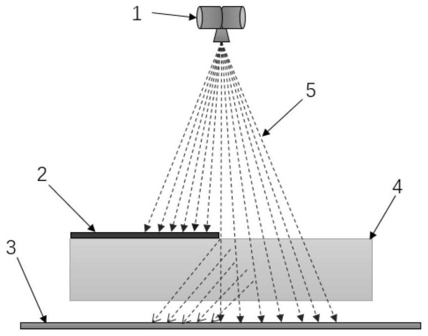
[0092] Wherein, the preset scattering simulation model is a physical model, such as image 3 As shown, the preset scattering simulation model includes a ray source 1, a lead plate 2, a flat panel detector 3, a phantom 4, and an X-ray 5; the ray source 1 and the flat panel detector 3 build a shooting environment, and the source image distance SID is set as 1.5 meters, the phantom 4 can use a material similar to the radiation attenuation characteristics of the human body to simulate the human body, in the present embodiment, use PMMA (polymethyl methacrylate, polymethyl methacrylate) material as the phantom 4 of the simulated human body, and set the phantom 4. The distance from ...

Embodiment 2

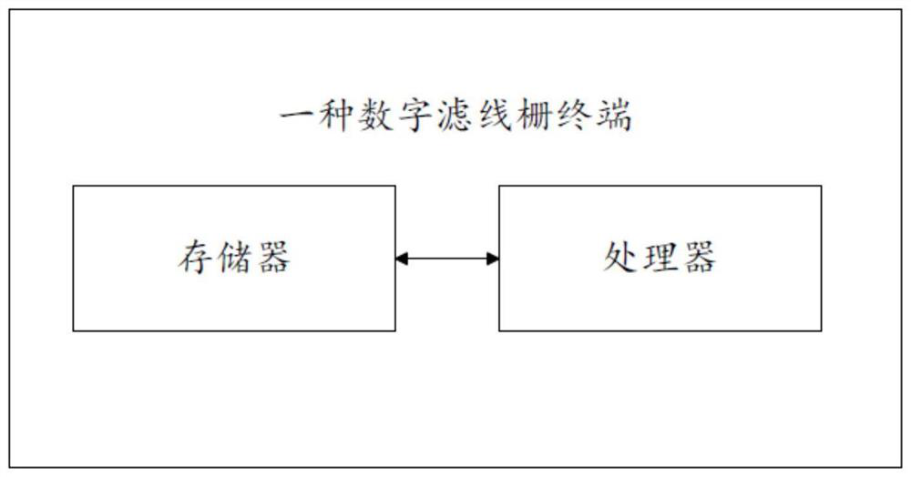
[0166] Please refer to figure 2 , a digital grid terminal in this embodiment includes a memory, a processor, and a computer program stored in the memory and operable on the processor, and the first embodiment is implemented when the processor executes the computer program Steps in the digital grid method in .

[0167] In summary, a digital grid method and terminal provided by the present invention determine a simulated boundary spread function curve based on a preset scattering simulation model, and fit the simulated boundary spread function curve to obtain a scattering model; A scatter correction request of the medical image to be corrected; obtaining a second tube voltage and a second body thickness corresponding to the medical image to be corrected according to the scatter correction request; based on the scatter model, the second tube voltage and the first The two-body thickness is calculated to obtain a scattering boundary spread function curve corresponding to the medi...


PUM


Abstract

The invention discloses a digital grid method and a terminal, and the method comprises the steps: determining a simulated boundary spread function curve based on a preset scattering simulation model, and carrying out the fitting of the simulated boundary spread function curve, and obtaining a scattering model; receiving a scattering correction request of a to-be-corrected medical image; according to the scattering correction request, a scattering boundary spread function curve corresponding to the to-be-corrected medical image is obtained through calculation based on the scattering model and the to-be-corrected medical image, and a scattering kernel is determined according to the scattering boundary spread function curve; scattering correction is carried out on the to-be-corrected medical image based on the scattering core, a corrected medical image is obtained, a digital grid is achieved, a physical simulation model of scattered rays is analyzed, a simulated ESF curve is determined, the scattering model can better reflect the physical effect of scattering and better fit the actual scattering condition, and the medical image correction accuracy is improved. And the scattering influence in the medical image is suppressed more effectively and thoroughly, so that the scattering influence in the medical image is effectively eliminated.

Description

technical field [0001] The invention relates to the technical field of medical image processing, in particular to a digital grid method and a terminal. Background technique [0002] For X-ray images, when the object is thicker and denser, the ray energy needs to be higher to penetrate the object and form an effective image contrast. But when the ray energy is higher and the object density is higher, the ray is more likely to scatter. When the X-scattered rays are irradiated on the detector, they will be superimposed on the original straight rays to form an image together, resulting in a non-linear increase in the gray level of the image, forming a local fog, and affecting the real contrast of the image. Therefore, how to eliminate the scattering effect of the image is very important. . [0003] At present, the physical grid method is mainly used to suppress X-scattered rays. This method uses a metal plate made of special materials, and the special-structured ray attenuatin...

Claims


Application Information

Patent Timeline
Patent Type & Authority Applications(China)
IPC IPC(8): G06T7/00G06T5/00G06T3/40
CPCG06T7/0012G06T3/4007G06T2207/10116G06T5/80
Inventor 陈磊
Owner 安健科技(重庆)有限公司
Learn More