Track mark positioning method

A positioning method and track marking technology, which is applied in the direction of instruments, conveyors, computer parts, etc., can solve the problem of low positioning accuracy of marking points

Pending Publication Date: 2022-03-29
GUANGDONG ATHENE ROBOTIC TECH CO LTD
View PDF0 Cites 0 Cited by
  • Summary
  • Abstract
  • Description
  • Claims
  • Application Information

AI Technical Summary

Problems solved by technology

[0005] The main purpose of the present invention is to provide a track marking positioning method to solve the pro

Method used


Image

  • Track mark positioning method
  • Track mark positioning method
  • Track mark positioning method

Examples


Embodiment Construction

[0026] It should be noted that, in the case of no conflict, the embodiments in the present application and the features in the embodiments can be combined with each other. The present invention will be described in detail below with reference to the accompanying drawings and examples.

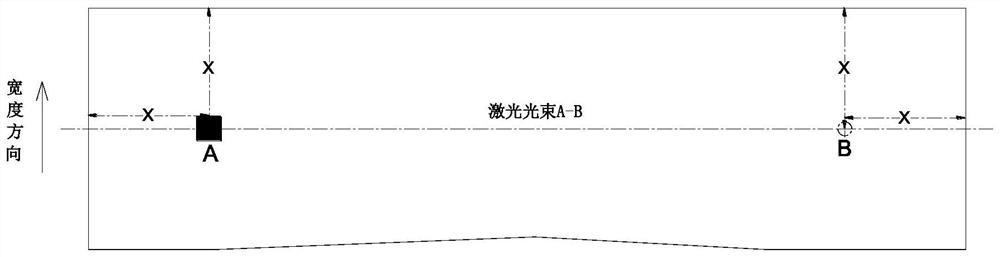
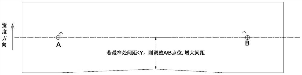
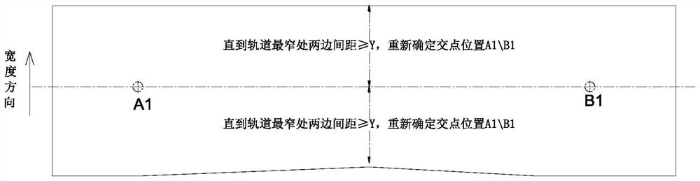
[0027] For a track marking positioning method provided by the present invention, please refer to Figure 1 to Figure 6 , including: setting the reference line on the track; measuring the minimum vertical distance between the reference line and the side of the track, and comparing the minimum vertical distance with the predetermined distance Y; according to the comparison result, adjusting the position of the reference line until the minimum vertical distance is greater than Or equal to Y, set the marker point on the straight line where the adjusted reference line is located; or, according to the comparison result, directly set the marker point on the straight line where the reference line is lo...


PUM


Abstract

The invention provides a track mark positioning method. The track mark positioning method comprises the steps that a datum line is arranged on a track; measuring a minimum vertical distance between the reference line and the side surface of the track, and comparing the minimum vertical distance with a predetermined distance Y; according to the comparison result, the position of the datum line is adjusted until the minimum vertical distance is larger than or equal to Y, and an identification point is arranged on the straight line where the adjusted datum line is located; or, according to the comparison result, directly setting an identification point on the straight line where the reference line is located. According to the invention, the problem of low positioning precision of the identification point of the two-dimensional code pasted on the track in the prior art is solved.

Description

technical field [0001] The present invention relates to the technical field of cloud track trolley positioning, in particular to a track identification positioning method. Background technique [0002] In the catering industry, with the continuous development of intelligence, many restaurants use the way of arranging hanging rails to serve meals, which can not only save manpower, but also provide customers with novel visual effects. [0003] When the trolley is running on the track, it relies on the two-dimensional code of the track paving coordinates for positioning. In the existing positioning method for the two-dimensional code, it is usually only based on the length and level of the track itself, and the ink line is popped up on the track as a reference. Auxiliary line to determine the position of each QR code identification point. [0004] However, in the above method, the level of the track is too dependent, and the error caused by the bending of the track during the ...

Claims


Application Information

Patent Timeline
IPC IPC(8): B65G35/00G06K17/00
CPCB65G35/00G06K17/00
Inventor 肖海潘林春李舒宜宝张黎明杨永章金峥黄喆
Owner GUANGDONG ATHENE ROBOTIC TECH CO LTD
Why Eureka
Try Eureka