Material taking mechanism

A material-retrieving mechanism and material technology, applied to conveyors, conveyor objects, transportation and packaging, etc., can solve the problems of low automation and low efficiency, and achieve the effect of improving operation efficiency and automation

Pending Publication Date: 2022-03-29
SHENNAN CIRCUITS
0 Cites 0 Cited by

AI-Extracted Technical Summary

Problems solved by technology

[0004] The material retrieving mechanism provided by this application can solve the problems of low effic...

Method used

In a specific embodiment, referring to Fig. 6, Fig. 6 is a schematic diagram of the positional relationship between the first clamping assembly and the second clamping assembly provided by an embodiment of the application; the clamping assembly 111 includes the first clamping The holding assembly 1111 and the second holding assembly 1112, and the first holding assembly 1111 and the second holding assembly 1112 are inclined at a preset angle, so that the first holding assembly 1111 and the second holding assembly 1112 can pass through the 30 clamps the material 30 at different positions; in a specific embodiment, the angle between the first clamping component 1111 and the second clamping component 1112 is 90 degrees, so as to avoid the material 30 as much as possible during the clamping process. Tilt occurs.
The material retrieving mechanism 10 that present embodiment provides, by setting retrieving assembly 11, retrieving assembly 11 is set to comprise driving assembly 112 and the holding assembly 111 that is connected with driving assembly 112, to pass holding assembly 111 abuts against the inner sidewall of the central hole 31 of the material 30 and clamps the material 30, and the driving assembly 112 drives the clamping assembly 111 to move along the radial direction of the central hole 31 to abut against or break away from the inner sidewall of the central hole 31, thereby Realize the grasping or placing of material 30; Simultaneously, by arranging moving assembly 12, retrieving assembly 11 is arranged on the mobile end of moving assembly 12, so that the material 30 clamped by retrieving assembly 11 is moved from the first position by moving assembly 12 Transported to the second position, thereby realizing the transport of the material 30, compa...

Abstract

The invention provides a material taking mechanism. The material taking mechanism comprises a material taking assembly and a moving assembly. The material taking assembly comprises a driving assembly and a clamping assembly connected with the driving assembly. The clamping assembly is used for abutting against the inner side wall of the center hole so as to clamp materials. The driving assembly is used for driving the clamping assembly to move in the radial direction of the center hole so as to abut against or break away from the inner side wall of the center hole. The material taking assembly is arranged at the moving end of the moving assembly, and the moving assembly is used for carrying the materials clamped by the material taking assembly from the first position to the second position. According to the material taking mechanism, the working efficiency can be greatly improved, and the automation degree can be effectively improved.

Application Domain

Technology Topic

Image

  • Material taking mechanism
  • Material taking mechanism
  • Material taking mechanism

Examples

  • Experimental program(1)

Example Embodiment

[0024] Next, the technical solutions in the present application embodiment will be described in the present application embodiment, and it is clear that the described embodiments are intended to be a part of the embodiments of the present application, not all of the embodiments. Based on the embodiments in the present application, one of ordinary skill in the art is in the scope of the present application without making creative labor premistence.
[0025] The terms "first", "second", "third" in this application are intended to describe purposes, and cannot be understood as an indication or implies relative importance or implicitly indicated the number of technical features indicated. Thereby, the features of "first", "second", and "third" are defined, and may be indicated or implied with at least one of this feature. In the description of the present application, the meaning of "multiple" is at least two, such as two, three, etc., unless otherwise specifically defined. All directional instructions (such as above, lower, left, right, front, and post, ...) in this application embodiment are only used to explain the relative positional relationship between the components under a particular attitude (as shown in the accompanying drawings). , Movement conditions, if the specific posture changes, the directional indication is also correspondingly changed. Moreover, the terms "including" and "have" and any variations, intended to cover the inclusion of his inclusion. For example, a series of processes, methods, systems, products, or devices that include a series of steps or units are not limited to the listed steps or units, but optionally, there is also a step or unit that is not listed, or optionally also include For these processes, methods, products, or other steps or units inherent.
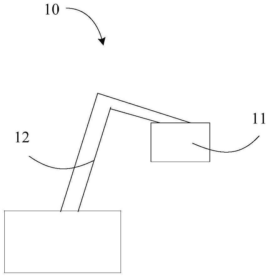
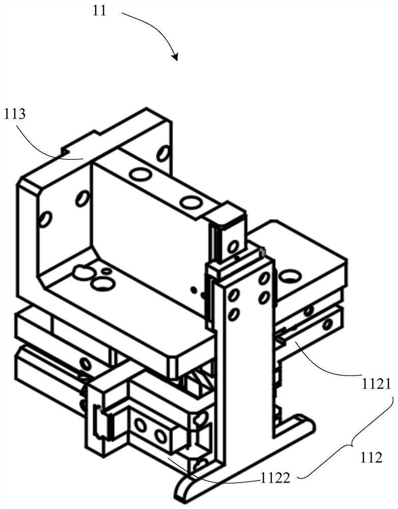
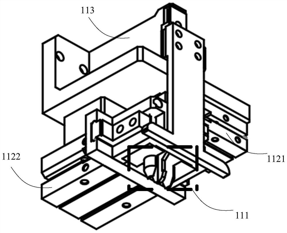
[0026] The "Embodiment" mentioned herein means that the specific features, structures, or characteristics described in connection with the embodiments may be included in at least one embodiment of the present application. This phrase is not necessarily a separate or alternative embodiment of the same embodiment in each position in the specification. Those skilled in the art is, and the embodiments described herein may be combined with other embodiments.
[0027] The present application will be described in detail below with reference to the accompanying drawings and examples.
[0028] See Figure 1 to 5 ,in, figure 1 The overall structure of the applet mechanism of the material provided herein is an embodiment of the apparatus. figure 2 A structural diagram of the first visual of the refueling assembly provided herein; image 3 A structural diagram of the second visual attachment of the refueling assembly provided herein; Figure 4 A structural diagram of the third visual attraction of the refueling assembly provided herein; Figure 5 A schematic view of the clamping member extends into the center hole of the apparatus provided herein; in the present embodiment, a substrate 10 of which is provided, and the applet mechanism 10 of the material can be used for taking place and handling. Material 30, such as taking place and handling the disk material 30 in surface mount technology, can greatly improve productivity and automation than manually taking place and handling material 30. Specifically, the applet mechanism 10 of the material includes a tetrane assembly 11 and a moving assembly 12.
[0029] Wherein, the applet assembly 11 is used to clamp the material 30 having a central hole 31, and the apparatus 11 is specifically disposed at the moving end of the moving assembly 12 to pass the material 30 of the refining assembly 11 from the moving assembly 12 from The first position is transported to a second position distinguished from the first position. Compared to artificial taking place and handling material 30, the work efficiency can be greatly improved and the degree of automation is improved. Among them, the moving assembly 12 can be a robot arm or robot.
[0030] Specifically, the refryrome 11 can extends into the central aperture 31 of the material 30 and abut against the inner side wall of the central aperture 31 to clamped material 30; wherein the central aperture 31 can be a through hole or material 30 through the upper and lower surfaces of the material 30. The blind hole, this embodiment does not limit this.
[0031] Specifically, the refryrome assembly 11 includes a clamp assembly 111 and a driving assembly 112; wherein the clamp assembly 111 is configured to clamping the material 30 in the inner side wall of the central aperture 31; and the clamp assembly 111 is connected to the drive assembly 112. To drive the clamp assembly 111 in the radial direction of the central hole 31 by driving the clamp assembly 112, the clamping assembly 111 abuts or disengages the inner side wall of the center hole 31; specifically, when the material is needed, the drive is required. The assembly 112 drives the clamp assembly 111 in a direction toward the inner side wall of the center hole 31 to abut against the inner side wall of the central aperture 31 to clamp the batch; when the material is required, the drive assembly 112 drives the clamp assembly 111 toward The movement is moved away from the inner side wall of the center hole 31 to remove the clamping assembly 111 from the inner side wall of the center hole 31 to place the material 30.
[0032] In a specific embodiment, see Image 6 , Image 6 A schematic diagram of the positional relationship between the first clamp assembly and the second clamp assembly provided herein; the clamp assembly 111 includes a first clamp assembly 1111 and a second clamp assembly 1112, and the first clamping The assembly 1111 and the second clamp assembly 1112 are inclined in a preset angle to clamp the material 30 through the first clamp assembly 1111 and the second clamp assembly 1112; in a specific embodiment In the middle, the angle between the first clamp assembly 1111 and the second clamp assembly 1112 is 90 degrees to avoid the inclinement of the material 30 during the clamping process.
[0033] Specifically, see Image 6The first clamp assembly 1111 can specifically include relative first left clamp 211 and the first right clamp 212, and the first left clip 211 and the first right clamp 212 can be moved back. Or relatively moving to abut against the inner side wall of the center hole 31, respectively or, respectively. The second clamp assembly 1112 may also include opposing the second left clip 213 and the second right clamp 214, and the second left clip 213 and the second right clamp 214 can also move back. Or relatively moving to abut against the inner side wall of the center hole 31, respectively or, respectively.
[0034] In a specific embodiment, see Figure 5 and Image 6 The first left clip 211, the first right clamp 212, the second left clip 213, and the second right clamp 214 can be a rod structure, and the rod structure can include axial connection. The abutting portion 311 and the entry portion 312; wherein the outer side wall of the abutting portion 311 is parallel to the inner side wall of the central aperture 31 for abutting with the inner side wall of the center hole 31 after extending into the center hole 31. The radial dimension of 312 gradually decreases from one end of the abutment portion 311 to one end of the abutting portion 311 to facilitate the clamp assembly 111 in the central aperture 31 of the material 30.
[0035] Specifically, see Figure 1 to 4 In this embodiment, the drive assembly 112 can specifically include a first driving member 1121 and a second drive member 1122; wherein the first driving member 1121 is connected to the first left clip 211 and the first right clamp 212. Used to drive the first left clip 211 and the first right clamp 212 relative to move or relative movement; the second drive member 1122 is connected to the second left clip 213 and the second right clamp 214 for Drive the second left clip 213 and the second right clamp 214 to move relative to moving or in the back. During the specific implementation, the first driving member 1121 and the second drive member 1122 may be activated to drive the first clamp assembly 1111 and the second clamp assembly 1112; of course, in other embodiments, the first driver 1121 and the second drive member 1122 can also be activated simultaneously to drive the first clamp assembly 1111 and the second clamp assembly 1112, respectively.
[0036] In the specific embodiment, see figure 2 The tetrane assembly 11 further includes a base 113, and the pickup assembly 11 is specifically provided by the chassis 113 on the moving end of the moving assembly 12; specifically, the moving end of the moving assembly 12 is connected to one side surface of the base 113, the first drive 1121 The second drive member 1122 is disposed on one side surface of the base 113 away from the moving end of the moving assembly 12, and the first driving member 1121 is disposed in the first direction, and the second drive member 1122 is set in the second direction, and the first direction is perpendicular to the first direction. The second direction is driven to move the first clamp assembly 1111 and the second clamp assembly 1112 in two mutually perpendicular directions, so that the first clamp assembly 1111 and the second clamp assembly 1112 can be in the center hole 31. The different locations are clamped.
[0037] Specifically, the first driving member 1121 and / or the second drive member 1122 can be a cylinder.
[0038] The feed mechanism 10 of the material provided in this embodiment is provided by providing the pick assembly 11, and the tether 112 includes a drive assembly 112 and a clamp assembly 111 connected to the drive assembly 112 to pass the clamping assembly 111 and the material. The inner side wall of the center hole 31 abuts and holds the material 30 by driving the clamp assembly 111 in the radial direction of the central hole 31 to abut or disengage the inner side wall of the center hole 31, thereby achieving material 30. Grab or placement; at the same time, by providing the moving assembly 12, the feed assembly 11 is disposed on the moving end of the moving assembly 12 to carry the material 30 sandwiched by the refueling assembly 11 from the first position from the first position to the first position. Two positions, thereby realizing the handling of material 30, compared to the prior art, the apparatus 10 of the material is greatly improved by the material 30, which greatly enhances the work efficiency and automation of the material 30. .
[0039] In one embodiment, see Figure 7 , Figure 7 A structural diagram of a clamp assembly provided in the present application; material 30 has a first surface and a second surface provided in the first surface opposite, and the central aperture 31 can specifically be a pass through the first surface and the second surface. Hole; In a specific embodiment, the clamp assembly 111 extends from the first surface of the material 30 and extends from the second surface of the material 30; in this embodiment, the first left clip 211, The first right clamp 212, the second left clip 213, and the second right clamp 214 are provided on at least one clamping member, and the stop 215 is specifically disposed on the clamping member away from moving. One end of the moving end of the assembly 12 to hold material 30 by the stopper member 111 by the stopper 215.
[0040] Specifically, the stop 215 is disposed in the axial direction perpendicular to the clamping member, extends toward the inner side wall of the center hole 31 to abrupt the horns to the inner side wall of the center hole 31, stop The member 215 can contact the second surface of the material 30 to give the material 30 vertically upward support, thereby preventing the balance of the clamping assembly 111 from being lowered, and there is a problem that the material 30 falls; specifically, stop The length dimension of the member 215, that is, the length size extension in the radial direction of the center hole 31 is smaller than the radial dimension of the central hole 31 so that the clamp assembly 111 can enter the central hole 31; specifically, The length dimension of the stop 215 is less than one-half of the central hole 31, and one end of the stop 215 is connected to the clamping member, and the other end of the stop member 215 extends toward the inner side wall of the center hole 31.
[0041] In a specific embodiment, the stopper 215 has a first surface and a second surface provided with the first surface opposite to the clutch extension into the center hole 31 and abuts against the inner side wall of the central hole 31. The first surface of the block 215 is in contact with the second surface of the material 30; specifically, the first surface of the stop 215 is parallel to the second surface of the material 30 to contact the stop 215 and the second surface of the material 30. When the stopper 215 can be completely bonded to the surface of the material 30 to prevent scratches from the second surface of the material 30.
[0042] In this embodiment, the applet mechanism 10 of the material provided is compared to the feed mechanism 10 of the material provided by the above embodiment, not only by the inside of the inner side wall of the material 30, not only by the inner side wall of the center hole 31 of the material 30. 30, and drive the clamping assembly 111 in the radial direction of the central hole 31 to abut or disengage from the inner side wall of the central hole 31 in the radial direction of the center hole 31, thereby achieving the gripping or placement of the material 30; at the same time, it is possible to pass the moving assembly 12 The material 30 sandwiched by the tetrane assembly 11 is transported from the first position to the second position, thereby realizing the handling of material 30, which greatly enhances the work efficiency and automation of the taking place and handling material 30; further, through the clip The holder is away from one end of the moving assembly 12 to extend the stopper 215 in the direction adjacent to the inner side wall of the center hole 31 to abrupt the clamping member and the inner side wall of the central hole 31. Stop The member 215 can contact the second surface of the material 30 to give the material 30 vertically upward support, thereby preventing the surface of the material 30 from falling, and effectively improves the clamping force when the clamping force of the clamp assembly 111 is small. The stability of the component 111 is sandwicked.
[0043] In a specific embodiment, the stop 215 can be integrally formed with the clamping member.
[0044] The above is only the embodiments of the present application, and it is not limited to the patent scope of the present application, and an equivalent structure or equivalent process transform is used to use the present application and the accompanying drawings, or use it directly or indirectly in other related technical fields. All of them are included within the patent protection range of the present application.

PUM

no PUM

Description & Claims & Application Information

We can also present the details of the Description, Claims and Application information to help users get a comprehensive understanding of the technical details of the patent, such as background art, summary of invention, brief description of drawings, description of embodiments, and other original content. On the other hand, users can also determine the specific scope of protection of the technology through the list of claims; as well as understand the changes in the life cycle of the technology with the presentation of the patent timeline. Login to view more.

Similar technology patents

Urban drainage pumping station remote information centralized management system

InactiveCN107766950AImprove safety and reliabilityImprove operational efficiency and automationData processing applicationsAutomatic controlBackground information
Owner:合肥清原自控科技有限公司

Classification and recommendation of technical efficacy words

  • Improve operational efficiency and automation

Urban drainage pumping station remote information centralized management system

InactiveCN107766950AImprove safety and reliabilityImprove operational efficiency and automationData processing applicationsAutomatic controlBackground information
Owner:合肥清原自控科技有限公司
Why Eureka
Try Eureka