
Server temperature control method and device based on expected temperature and storage medium

A server and power consumption technology, which is applied to instruments, forecasting, relational databases, etc., can solve the problems of short server temperature, increased heat dissipation, and increased power consumption, so as to avoid excessive local temperature, avoid extra energy consumption, and reduce fan speed. Effect

Pending Publication Date: 2022-03-29
SUZHOU LANGCHAO INTELLIGENT TECH CO LTD
View PDF0 Cites 0 Cited by
  • Summary
  • Abstract
  • Description
  • Claims
  • Application Information

AI Technical Summary

Problems solved by technology

However, the existing problems in the prior art are: in the prior art, the temperature is first measured by the temperature sensor in the server, and then the fan speed is adjusted according to the temperature. The control process of the fan speed has an inevitable hysteresis compared with the heat generation process.
This kind of hysteresis causes the existing technology to face the situation of increased power consumption and temperature rise, and the heat dissipation cannot be improved following the increase of power consumption, which may cause the actual temperature of the server to temporarily exceed the temperature limit range
This kind of hysteresis causes the existing technology to face the situation of lower power consumption and lower temperature, and the heat dissipation cannot be reduced due to the reduction of power consumption by dipping, which makes the fan generate additional energy consumption.

Method used


Image

  • Server temperature control method and device based on expected temperature and storage medium
  • Server temperature control method and device based on expected temperature and storage medium
  • Server temperature control method and device based on expected temperature and storage medium

Examples


Embodiment 1

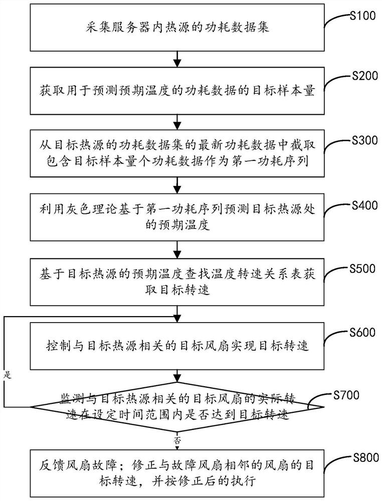
[0046] refer to figure 1 As shown, the embodiment of the present invention provides a server temperature control method based on expected temperature, including:

[0047]S100, collect the power consumption data set of the heat source in the server, specifically, collect the current data of the components in each heat source in time sequence through the current sensors distributed at the heat source in the server, and multiply the current data of each component in the heat source by the working voltage And accumulate to form a power consumption data set, the timing of the power consumption data and current data in the formed high power consumption data set is consistent.

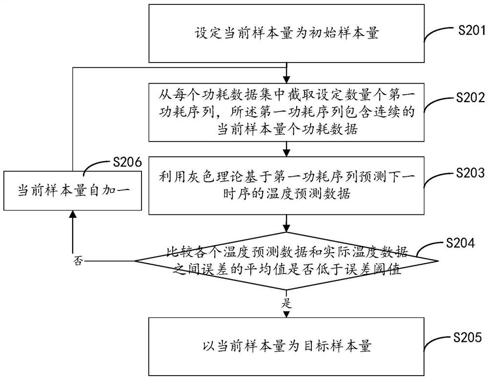
[0048] S200, acquire the target sample size of the power consumption data used to predict the expected temperature; during the specific implementation process, refer to figure 2 As shown, methods for obtaining target sample sizes include:

[0049] S201. Set the current sample size as the initial sample siz...

Embodiment 2

[0086] refer to Figure 4 As shown, the embodiment of the present application provides a server temperature control device based on the expected temperature, including: a current collection module, the current collection module collects the current data of the heat source in the server in time sequence;

[0087] A power consumption calculation module, the power consumption calculation module uses the current data collected by the current acquisition module to multiply the corresponding operating voltage to calculate the power consumption of the heat source;

[0088] A prediction module, the prediction module obtains the first power consumption sequence from the power consumption data of each heat source and then processes and forms the second power consumption sequence, performs temperature prediction according to the gray theory according to the first power consumption sequence and the second power consumption sequence to obtain the expected temperature ;

[0089] An executi...

Embodiment 3

[0095] An embodiment of the present invention provides a medium for implementing a server temperature control method based on an expected temperature. The medium for implementing the server temperature control method based on the expected temperature stores at least one instruction, and reads and executes the instruction to implement the server temperature control method based on the expected temperature.

[0096] The present invention uses gray theory to predict the expected temperature at the target heat source in the server according to the first power consumption sequence of the target heat source, queries the temperature and speed relationship table according to the expected temperature, obtains the target speed, and controls the target fans related to the target heat source to achieve the target speed. According to the prediction of gray theory, the expected temperature can be obtained before the power consumption changes, and then the fan speed is controlled according to...


PUM


Abstract

The invention relates to a server temperature control method and device based on expected temperature and a storage medium. Current sensors distributed at heat sources in a server collect current data of each heat source according to a time sequence, and the current data of each component in the heat sources are multiplied by working voltage and accumulated to form a power consumption data set; intercepting a first power consumption sequence containing the power consumption data of the target sample size from the latest power consumption data of the power consumption data set of the target heat source; predicting an expected temperature at the target heat source based on the first power consumption sequence by using a grey theory; searching a temperature-rotating speed relation table based on the expected temperature of the target heat source to obtain a target rotating speed; and controlling a target fan related to the target heat source to achieve the target rotating speed. According to the method, the fan can be controlled to increase the rotating speed in time in the process of increasing the power consumption, so that the actual temperature of the server cannot exceed the temperature limit range, and the fan speed can be reduced in time in the process of reducing the power consumption, so that additional energy consumption is avoided.

Description

technical field [0001] The present invention relates to the technical field of server temperature control, in particular to a server temperature control method, device and storage medium based on an expected temperature. Background technique [0002] In addition to performance, the selection of servers has always been a priority for stability, and heat dissipation is an important key factor affecting the stable operation of the server. [0003] At present, the server heat dissipation control strategy is to use the temperature sensors distributed at each heat source of the server to measure the temperature data, preset the relationship between the temperature threshold and the fan speed, compare the temperature data and the temperature threshold to select the fan speed, and increase or decrease the fan speed to achieve Heat the server to provide a stable temperature environment so that the operating temperature of the server is within the limits of its design. However, there...

Claims


Application Information

Patent Timeline
IPC IPC(8): G06F1/20G06F16/2455G06F16/28G06Q10/04
CPCG06F1/206G06F16/2455G06F16/284G06Q10/04Y02D10/00
Inventor 韩钟兴
Owner SUZHOU LANGCHAO INTELLIGENT TECH CO LTD
Learn More