
Wireless debugging method, system and device

A debugging method and technology for debugging systems, which are applied in wireless communication, software testing/debugging, digital data information retrieval, etc., can solve problems such as inability to debug, cumbersome operations, and increase equipment production costs, and achieve the freedom of debugging locations or distances. Simple operation effect

Pending Publication Date: 2022-03-29
GUANGZHOU LANGO ELECTRONICS TECH CO LTD
View PDF0 Cites 0 Cited by
  • Summary
  • Abstract
  • Description
  • Claims
  • Application Information

AI Technical Summary

Problems solved by technology

[0003] Debugging through the serial port needs to use a serial port cable to connect to the developer's computer, which is limited by the serial port transmission distance and the cable, and requires the developer to debug near the device. This debugging method is limited by the geographical distance; and through The way of network ADB connection to the device requires that the network or WiFi connected to the device and the network or WiFi connected to the developer’s computer must be kept in the same network segment. In most cases, the device does not have the conditions to connect to the wired network, such as production line, no network In office scenarios, etc., at this time, the device cannot connect to the network, so it cannot be debugged through the network ADB debugging method; for WiFi networking, it is required to have a WiFi module on the device, which further increases the production cost of the device, and if the developer The object of debugging is the network condition of the device, so it cannot be debugged through the ADB debugging method
[0004] At the same time, connect the device through the serial port or network ADB for debugging. When encountering the need to upgrade the bin package, you need to manually copy the bin package from the developer’s computer to the U disk, and then insert it into the device and enter the command to upgrade. The operation is very cumbersome.

Method used


Image

  • Wireless debugging method, system and device
  • Wireless debugging method, system and device
  • Wireless debugging method, system and device

Examples


Embodiment Construction

[0041] Embodiments of the present disclosure will be described in detail below in conjunction with the accompanying drawings.

[0042] Embodiments of the present disclosure are described below through specific examples, and those skilled in the art can easily understand other advantages and effects of the present disclosure from the contents disclosed in this specification. Apparently, the described embodiments are only some of the embodiments of the present disclosure, not all of them. The present disclosure can also be implemented or applied through different specific implementation modes, and various modifications or changes can be made to the details in this specification based on different viewpoints and applications without departing from the spirit of the present disclosure. It should be noted that, in the case of no conflict, the following embodiments and features in the embodiments can be combined with each other. Based on the embodiments in the present disclosure, a...


PUM


Abstract

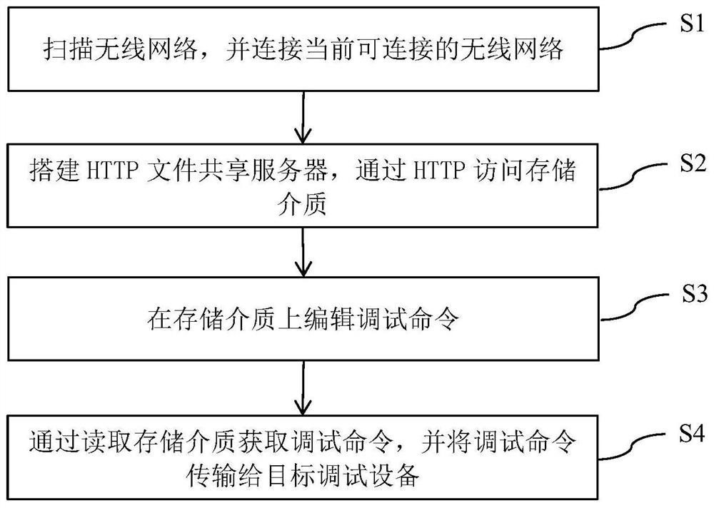
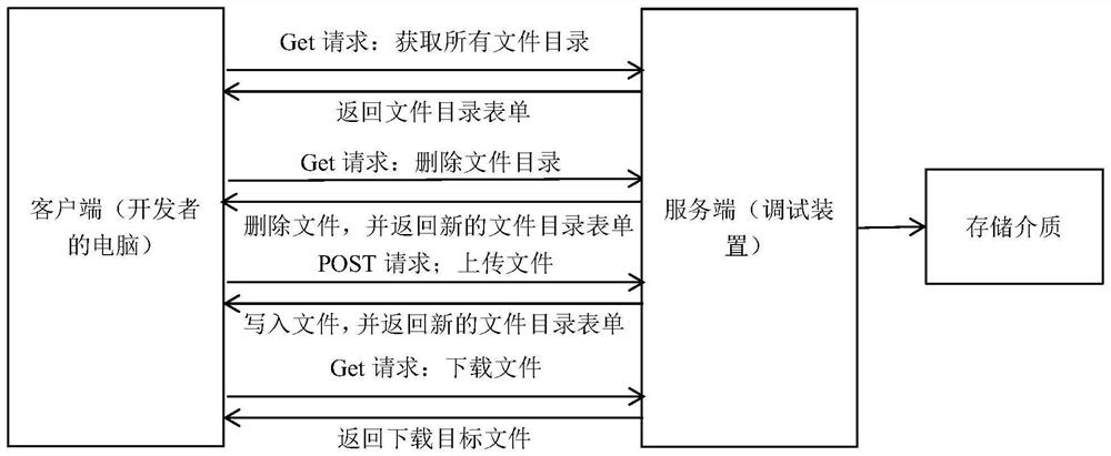
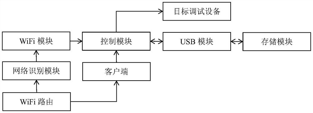
The invention discloses a wireless debugging method, system and device, and relates to the technical field of equipment debugging, and the method comprises the following steps: scanning a wireless network, and connecting a currently connectable wireless network; an HTTP file sharing server is established, and a storage medium is accessed through HTTP; editing a debugging command on the storage medium; and obtaining the debugging command by reading the storage medium, and transmitting the debugging command to the target debugging equipment. By installing a WiFi module on the debugging device, a developer computer and the debugging device are connected with the same network, a developer can communicate with the debugging device through the own computer, and by establishing an HTTP file sharing server, the developer computer can directly write a debugging command on a storage medium. The target debugging equipment can directly read the debugging command on the storage medium, so that the functions of upgrading, configuration and the like are realized, the wireless debugging of the target debugging equipment can be realized, and the debugging defects in the prior art are overcome.

Description

technical field [0001] The invention relates to the technical field of equipment debugging, in particular to a wireless debugging device and method. Background technique [0002] At present, in the development of the conference all-in-one machine, it is mainly connected to the device through the serial port or the network ADB for debugging, but these two debugging methods have great limitations. [0003] Debugging through the serial port needs to use a serial port cable to connect to the developer's computer, which is limited by the serial port transmission distance and the cable, and requires the developer to debug near the device. This debugging method is limited by the geographical distance; and through The way of network ADB connection to the device requires that the network or WiFi connected to the device and the network or WiFi connected to the developer’s computer must be kept in the same network segment. In most cases, the device does not have the conditions to conne...

Claims


Application Information

Patent Timeline
IPC IPC(8): G06F11/36G06F16/182H04W76/10
CPCG06F11/362G06F16/182H04W76/10
Inventor 朱红喜周顺陆
Owner GUANGZHOU LANGO ELECTRONICS TECH CO LTD
Learn More