Jig for accurately positioning upper lampshade of high-brightness backlight double-lampshade structure

A technology of backlight source and double lampshade is applied in the field of accurate lampshade positioning fixture on the structure of high brightness backlight source and double lampshade. Effect

Pending Publication Date: 2022-03-29
新谱(惠州)电子有限公司
View PDF0 Cites 0 Cited by
  • Summary
  • Abstract
  • Description
  • Claims
  • Application Information

AI Technical Summary

Problems solved by technology

[0005] The purpose of the present invention is to solve the situation that the relative position of the lampshade and the lamp holder cannot be fixed when the current position of the lampshade and the lamp holder are combined, resulting in the inability to connect and bumping the light pole and

Method used


Image

  • Jig for accurately positioning upper lampshade of high-brightness backlight double-lampshade structure
  • Jig for accurately positioning upper lampshade of high-brightness backlight double-lampshade structure
  • Jig for accurately positioning upper lampshade of high-brightness backlight double-lampshade structure

Examples


Embodiment 1

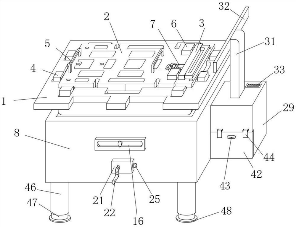
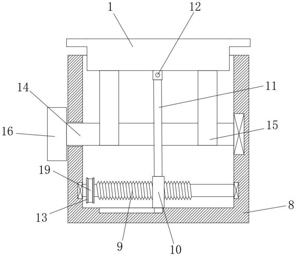
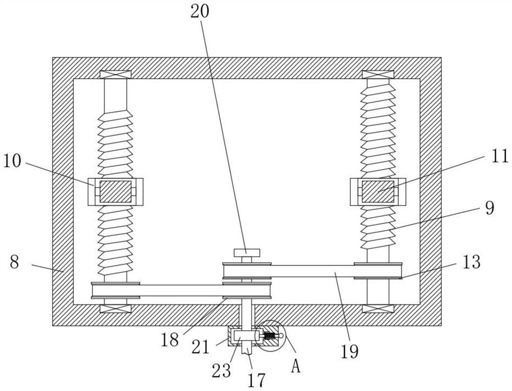
[0038] Embodiment 1: A high-brightness backlight double lampshade structure upper lampshade precise positioning jig, including a fixed seat 1, a positioning plate 2, a telescopic device, a limit block 3, a fixed block 4, a handle 5, a leveling device, a rotating device, a limiter Positioning device, dust suction device, air filter device, dust removal device, closing device and height adjustment device, the positioning plate 2 is set on the top of the fixed seat 1, and the telescopic device is configured to be connected with the positioning plate 2, and the telescopic device is installed on the right side of the top of the positioning plate 2, the limit block 3 is configured to be on the right side of the telescopic device, and the fixed block 4 is arranged on the fixed seat 1 around the top, the handle 5 is arranged on both sides of the top of the positioning plate 2, the rotating device is configured to cooperate with the leveling device, and the limiting device is configured...

Embodiment 2

[0039] Embodiment 2: This embodiment should be understood as at least including all the features of any one of the foregoing embodiments, and further improvements are made on the basis of it. Specifically, a high-brightness backlight double lampshade structure upper lampshade precision fixture is provided, including Fixed seat 1, positioning plate 2, telescopic device, limit block 3, fixed block 4, handle 5, leveling device, rotating device, limit device, dust suction device, air filter device, dust discharge device, closing device and adjustment High device, the positioning plate 2 is set on the top of the fixed seat 1, the telescopic device is configured to cooperate with the positioning plate 2, and the telescopic device is installed on the right side of the top of the positioning plate 2 side, the limiting block 3 is configured to be on the right side of the telescopic device, the fixing block 4 is arranged around the top of the fixing seat 1, and the handle 5 is arranged o...


PUM


Abstract

The invention relates to the technical field of medical cause display prevention and treatment, and discloses a high-brightness backlight double-lampshade structure upper lampshade accurate positioning jig. According to the embodiment, a limiting pin is pulled, a rotating shaft is driven to rotate through rotation of a rotating handle, so that a rotating wheel is driven to drive a screw to rotate through a belt, and a fixing base can be adjusted in the horizontal direction through a supporting rod; the dust suction device is matched with the air filtering device to work, dust on the surface of the lampshade and the surface of the lamp holder can be sucked, in the embodiment, through matched work of the dust exhaust device and the sealing device, dust collected in the collecting box can be conveniently treated and discharged, in the embodiment, supporting legs in the height adjusting device rotate, height adjustment is conducted along a threaded sleeve, and the dust exhaust efficiency is improved. The supporting legs are used for supporting, the whole device can be stably supported, and stable work of the device is guaranteed.

Description

technical field [0001] The invention relates to the technical field of medical display prevention and control, in particular to a precision jig for lampshade positioning on a double lampshade structure of a high-brightness backlight source. Background technique [0002] Medical displays and high-definition and high-brightness displays used in the medical industry, the maturity and popularity of PACS technology, and the rapid development of various digital imaging equipment such as DR, CR, multi-row CT, 3D images, etc., the purchase and configuration of medical displays has become The focus of attention of hospitals and PACS integrators, because the medical display is the final presenter of medical images in the digital system, it carries the replacement of film, ensures the image quality, and finally realizes the doctor's "soft reading" observation and diagnosis of patients. In the PACS system, all medical displays are required to be consistent and integrated. In many cases,...

Claims


Application Information

Patent Timeline
IPC IPC(8): G09F9/30
CPCG09F9/30
Inventor 赖志鹏刘建莉钟路军
Owner 新谱(惠州)电子有限公司
Why Eureka
Try Eureka