
Outer rotor brushless motor magnetic steel bonding tool and bonding method thereof

A technology of brushless motors and external rotors, applied in the direction of electromechanical devices, manufacturing motor generators, manufacturing stator/rotor bodies, etc., can solve the problem of improving the bonding efficiency of magnets and rotors, reducing the labor intensity of workers, and making it difficult to simplify Operation and other problems, to achieve the effect of easy bonding processing, good size adaptability, and simplified operation process

Pending Publication Date: 2022-03-29
安徽智鸥驱动科技有限公司
View PDF2 Cites 0 Cited by
  • Summary
  • Abstract
  • Description
  • Claims
  • Application Information

AI Technical Summary

Problems solved by technology

[0006] The purpose of the present invention is to provide a magnetic steel bonding tool for an outer rotor brushless motor and a bonding method thereof, so as to solve the problem in the above-mentioned background technology that it is difficult for personnel to cooperate or manually insert and install the magnetic steel and the rotor. Improve the bonding efficiency of the magnetic steel and the rotor, but cannot reduce the labor intensity of the staff, and it is difficult to simplify the operation problem

Method used


Image

  • Outer rotor brushless motor magnetic steel bonding tool and bonding method thereof
  • Outer rotor brushless motor magnetic steel bonding tool and bonding method thereof
  • Outer rotor brushless motor magnetic steel bonding tool and bonding method thereof

Examples


Embodiment 1

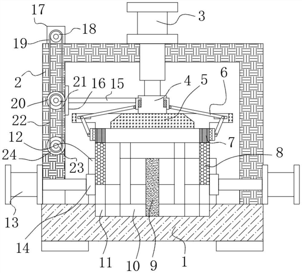
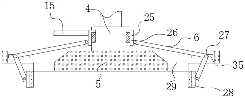
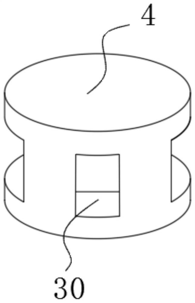
[0041] Embodiment 1: including the base 1 and the support plate 2, the support plate 2 is fixedly connected to the upper end surface of the base 1, the middle position of the upper end surface of the support plate 2 is provided with a cylinder one 3, and the lower end of the cylinder one 3 is provided with a pressing mechanism, the pressing mechanism The lower end of the base 1 is provided with a clamping mechanism, and the middle position of the upper end surface of the base 1 is provided with a bonding mechanism;

[0042] The bonding mechanism includes a positioning groove 10, a ring seat 12, a magnetic steel groove 11, a pressure plate 14, a cylinder 2 13, a positioning column 9 and a perforation 32, and the positioning groove 10 is provided at the middle position of the upper end surface of the base 1, and the circle The ring seat 12 is fixedly connected to the upper end surface of the base 1, and the ring seat 12 surrounds the outside of the positioning groove 10, the perf...

Embodiment 2

[0045] Embodiment 2: including the base 1 and the support plate 2, the support plate 2 is fixedly connected to the upper end surface of the base 1, the middle position of the upper end surface of the support plate 2 is provided with a cylinder one 3, the lower end of the cylinder one 3 is provided with a pressing mechanism, and the pressing mechanism The lower end of the base 1 is provided with a clamping mechanism, and the middle position of the upper end surface of the base 1 is provided with a bonding mechanism;

[0046] The bonding mechanism includes a positioning groove 10, a ring seat 12, a magnetic steel groove 11, a pressure plate 14, a cylinder 2 13, a positioning column 9 and a perforation 32, and the positioning groove 10 is provided at the middle position of the upper end surface of the base 1, and the circle The ring seat 12 is fixedly connected to the upper end surface of the base 1, and the ring seat 12 surrounds the outside of the positioning groove 10, the perf...


PUM


Abstract

The magnetic steel bonding tool comprises a base and a supporting plate, the supporting plate is fixedly connected to the upper end face of the base, a first air cylinder is arranged in the middle of the upper end face of the supporting plate, a pressing mechanism is arranged at the lower end of the first air cylinder, and a clamping mechanism is arranged at the lower end of the pressing mechanism; a bonding mechanism is arranged in the middle of the upper end face of the base. The bonding mechanism comprises a positioning groove, a circular ring seat, a magnetic steel groove, an abutting plate, a second air cylinder, a positioning column and a penetrating hole, the positioning groove is formed in the middle of the upper end face of the base, good size adaptability to the fixing ring is achieved, the operation efficiency is greatly improved, the operation process is simplified, follow-up bonding machining is facilitated, and the production efficiency is improved. When the magnetic steel and the rotor are bonded, the pressing operation on the connecting ring is not influenced, so that the assembled component is more stable, and the operation process is more stable.

Description

technical field [0001] The invention relates to the technical field of motor production, in particular to a magnetic steel bonding tool for an outer rotor brushless motor and a bonding method thereof. Background technique [0002] The brushless motor is composed of the main body of the motor and the driver, and is a typical mechatronic product; since the brushless DC motor operates in a self-controlled manner, it will not be on the rotor like a synchronous motor that starts under heavy load under variable frequency speed regulation. In addition, the starting winding will not cause oscillation and out of step when the load changes suddenly. When the brushless motor is processed, a layer of magnetic steel needs to be installed on the outer layer of the rotor. The rotor and the magnetic steel are bonded by glue, so its The bonding effect between them greatly affects the processing quality of brushless motors. [0003] For example, China Patent Application No. CN202021700012.2 ...

Claims


Application Information

Patent Timeline
Patent Type & Authority Applications(China)
IPC IPC(8): H02K15/03
CPCH02K15/03
Inventor 陈凡崔德新张志峰
Owner 安徽智鸥驱动科技有限公司
Learn More