Pin cut-off machine capable of improving machining efficiency easily

A technology of processing efficiency and cutting machine, applied in the field of cutting machine, can solve the problems of further improvement of resistance pin cutting efficiency, low production efficiency, low dimensional accuracy, etc., and achieves simple structure, high feeding efficiency and high processing. The effect of efficiency

Inactive Publication Date: 2015-03-25
CHENGDU ZHONGSHAN SCI & TECH
View PDF6 Cites 1 Cited by
  • Summary
  • Abstract
  • Description
  • Claims
  • Application Information

AI Technical Summary

Problems solved by technology

In the prior art, the length of the above pins is generally formed into the required size by manual cutting. The above cutting method has low production efficiency, low dimensional accuracy and high labor intensity.
In the prior art, there is a device specially used for cutting resistance leads. As shown in the invention patent with the authorized announcement number CN 203208586 U, a resistance lead wire cutting device is provided, which realizes the cutting of resistance leads. Mechanization, but the efficiency of resistor pin cutting needs to be further improved

Method used


Image

  • Pin cut-off machine capable of improving machining efficiency easily

Examples


Embodiment 1

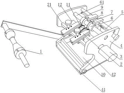
[0022] Such as figure 1 As shown, a kind of foot shearing machine that is conducive to improving processing efficiency includes a frame 4 and a cutter 6 arranged on the frame 4, and the shown frame 4 is also provided with a feeding device and a cutter 6 braking device;

[0023] The feeding device shown includes a toothed disc shaft 12 arranged on the frame 4, and a feeding toothed disc 11 keyed to the toothed disc shaft 12. The number of the shown feeding toothed discs 11 is four, and the feeding toothed discs 11 are all threaded. A toothed plate bolt for fixing the feeding toothed plate 11 is connected, and a driving part 3 for braking its rotation is also fixedly connected to the toothed plate shaft 12;

[0024] The shown cutter 6 is a disk-shaped structure provided with a central hole, and the frame 4 is also fixed with a cutter slide rail 61, the shown cutter 6 is matched with the cutter slide rail 61, and the number of the cutter 6 is two. One, the axis of cutter slide r...

Embodiment 2

[0029] The present embodiment is further limited on the basis of embodiment 1, as figure 1 As shown, in order to facilitate the assembly of the present invention, the frame 4 includes a bottom plate and two side plates 42 arranged on the bottom plate, wherein at least one side plate 42 is detachably connected. In the above structure, the bottom plate and one of the side plates 42 can be integrally arranged as a whole, which can be formed by casting or bending, and the frame 4 can be obtained by bolt connection between the two side plates 42, so that When the present invention is assembled, the feeding device and the cutter 6 braking device can be fixed on the fixed side plate 42 and then the installation of the detachable side plate 42 can be completed.

Embodiment 3

[0031] The present embodiment is further limited on the basis of embodiment 1, as figure 1As shown, in order to allow electronic components such as resistors and capacitors to accurately fall into the pin cutting support part, the frame 4 is also provided with a material traction part, and the traction part includes a traction rail 2 and an axis and a toothed disc shaft 12. An axis-parallel traction slide bar 21, the traction slide bar 21 is fixed on the frame 4, the traction rail 2 is fixed on the traction slide bar 21, and the position of the traction rail 2 on the traction slide bar 21 is adjustable. In the above structure, the traction rail 2 can be a plate-like, sheet-like or groove-like structure.

[0032] In order to maintain the position of the cutter 6 conveniently, a locking nut is threadedly connected to the cutter screw 5 , and the end of the locking nut is in contact with the frame 4 or the cutter block 7 . In the above structure, the purpose of fixing the cutter...


PUM


Abstract

The invention discloses a pin cut-off machine capable of improving machining efficiency easily. The pin cut-off machine comprises a machine frame and cutters arranged on the machine frame. A feeding device and a cutter braking device are further arranged on the machine frame. The feeding device comprises a fluted disk shaft and four feeding fluted disks. Fluted disk bolts are arranged on the feeding fluted disks, and a driving part is further arranged on the fluted disk shaft. A cutter sliding rail is further fixed to the machine frame, and the number of the cutters is two. The cutter braking device comprises two cutter clamping blocks, a clamping block rail and a cutter screw rod, and cutter clamping grooves are further formed in the cutter clamping blocks. The pin cut-off machine is simple in structure, high in machining efficiency, low in maintenance cost and suitable for various raw materials in different sizes.

Description

technical field [0001] The invention relates to the field of electronic component production equipment, in particular to a foot cutting machine which is beneficial to improve processing efficiency. Background technique [0002] With the increasing abundance of electronic products and the continuous improvement of functions, the use of electronic components is gradually increasing, and electronic products such as resistors and capacitors are indispensable parts for most resistor products. In the prior art, the following resistor fixing methods have appeared: resistor manufacturers fix multiple resistors with straps, that is, fix straps on the pins at both ends of the resistors to form a resistor string, so that the resistor pins can be fixed later as needed. length for efficient batch cutting or bending. In the prior art, the length of the above pins is generally formed into the required size by manual cutting. The above cutting method has low production efficiency, low dime...

Claims


Application Information

Patent Timeline
Patent Type & Authority Applications(China)
IPC IPC(8): B21F11/00B21F23/00
CPCB21F11/00B21F23/005
Inventor 李强彭恩文张建清
Owner CHENGDU ZHONGSHAN SCI & TECH
Why Eureka
Try Eureka