Device for purifying gas

A gas and intake pipeline technology, applied in the fields of inert gas compounds, inorganic chemistry, non-metallic elements, etc., can solve the problems of short utilization cycle, pause in the production process, low utilization rate of purified substances, etc. easy effect

Inactive Publication Date: 2013-02-06
HEILONGJIANG PROVINCE & RUSSIA IND TECH COOPERATION CENT
View PDF3 Cites 0 Cited by
  • Summary
  • Abstract
  • Description
  • Claims
  • Application Information

AI Technical Summary

Problems solved by technology

[0004] The present invention aims to solve the problem that the existing gas purification device has pauses in the production process, complex operation process, low utilization rate and short utilization period of the gas purification material in the device, which makes the gas purification efficiency low and the purified gas The purity cannot meet the technical problems of actual alloy production, and a device for purifying gas is provided

Method used


Image

  • Device for purifying gas
  • Device for purifying gas
  • Device for purifying gas

Examples


specific Embodiment approach 1

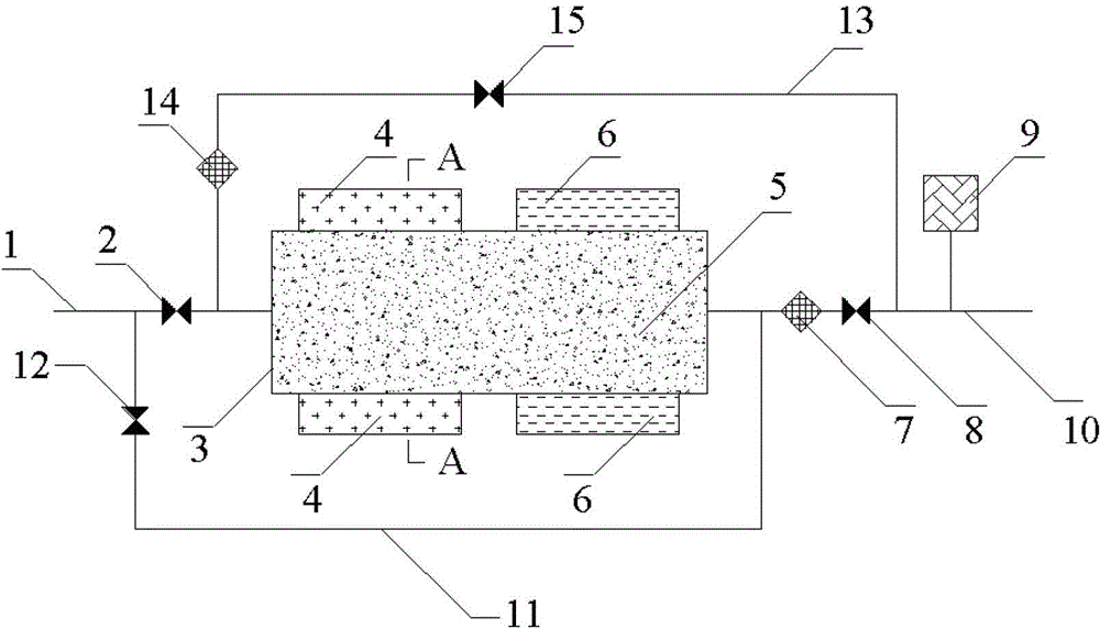
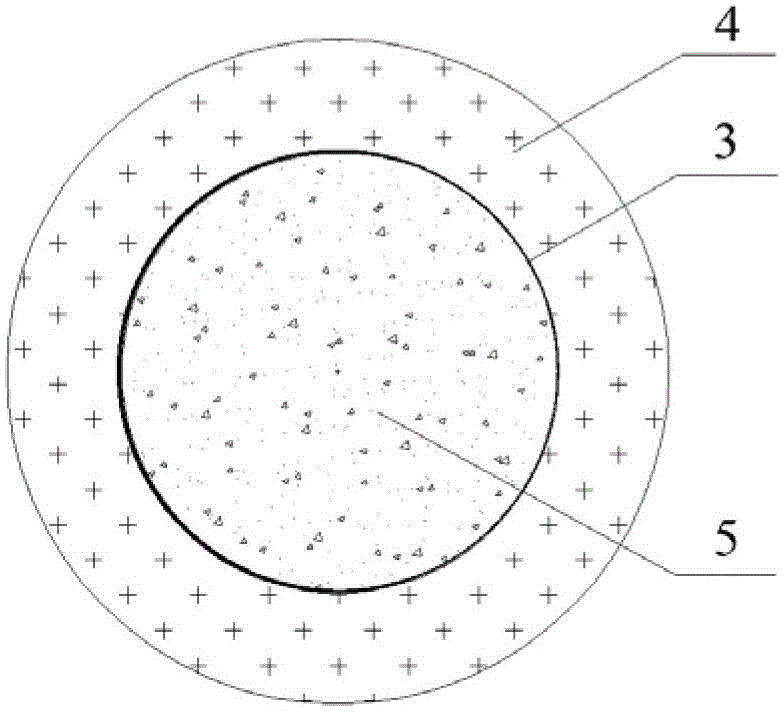
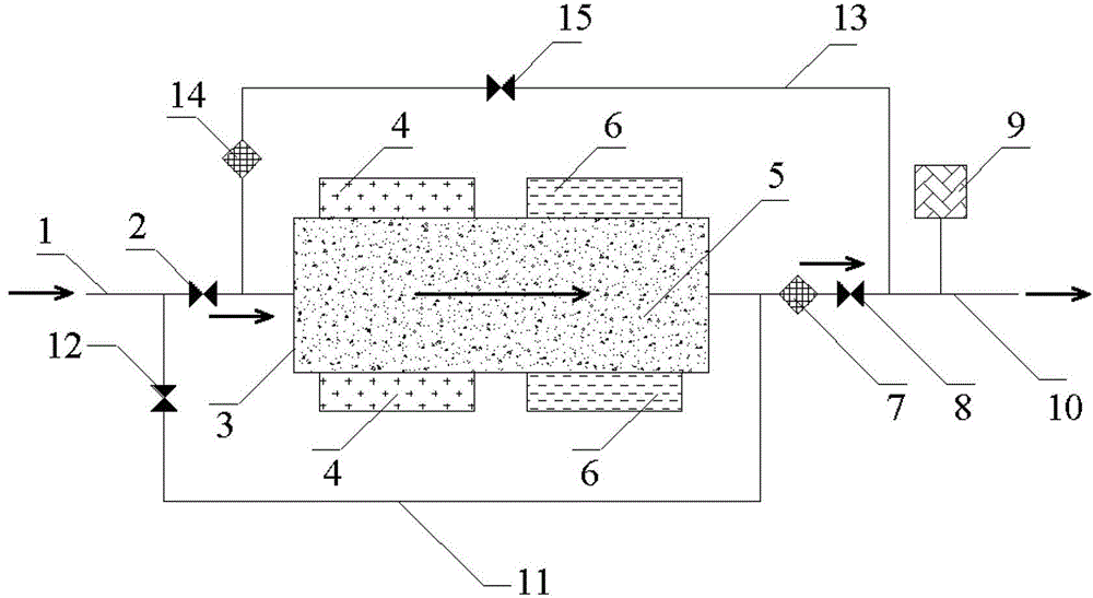
[0012] Specific implementation mode one: combine figure 1 , figure 2 , image 3 and Figure 4 , this embodiment is a device for purifying gas, a device for purifying gas, which is composed of an intake pipeline 1, a first valve 2, a reactor shell 3, a heater 4, particulate matter 5, a cooler 6, a second A filter 7, a second valve 8, a hygrometer 9, an outlet pipeline 10, a first bypass 11, a third valve 12, a second bypass 13, a second filter 14 and a fourth valve 15, wherein, The reactor housing 3 is cylindrical, and the reactor housing 3 is filled with particulate matter 5 for purifying the gas. The lower bottom surface is communicated, a heater 4 is set on the side of the left half of the reactor shell 3, and a cooler 6 is set on the side of the right half of the reactor shell 3, the heater 4 and the cooler 6 can exchange positions, On the gas pipeline 1, from left to right, there are three-way joint I connected to the starting end of the first bypass 11, the first val...

specific Embodiment approach 2

[0017] Embodiment 2: The difference between this embodiment and Embodiment 1 is that the particulate matter 5 is a mixture of calcium chips and ceramic particles. Others are the same as in the first embodiment.

[0018] The working mechanism of the purified gas that adopts the mixture of calcium chips and ceramic particles as the particulate matter 5 described in this embodiment is as follows: Process 1, the side of the left half of the reactor shell 3 is heated to the reactor shell by the heater 4 3. The calcium in the calcium chips in the left half of the interior evaporates. When the gas to be purified enters the reactor shell 3, it mixes with the calcium vapor. A part of the calcium vapor reacts with the impurities in the gas and becomes solid and deposits. The unreacted Part of the calcium vapor and the purified gas enter the right half of the reactor shell 3, and the side of the right half of the reactor shell 3 is cooled by the cooler 6, so that the unreacted part of th...

specific Embodiment approach 3

[0020] Embodiment 3: The difference between this embodiment and Embodiment 1 or 2 is that the mass ratio of calcium chips and ceramic particles in the particulate matter 5 is 1:(0.2~5). Others are the same as in the first or second embodiment.


PUM

PropertyMeasurementUnit
diameteraaaaaaaaaa

Abstract

A device for purifying gas relates to the field of devices for purifying gas. The device is used for solving the problems of the conventional device for purifying gas that the production process is not continuous, the operation process is complicated, the utilization rate of gas purifying substances in the device is low and the utilization cycle of the gas purifying substances is short, so the gas purification rate is low and the purity of the purified gas cannot meet the requirements of practical alloy production. The device for purifying gas consists of a gas inlet pipeline, a first valve, a reactor shell body, a ring type heater, particulate matters, a ring type cooler, a first filter, a second valve, a humidometer, a gas outlet pipeline, a first bypass, a third valve, a second bypass, a second filter and a fourth valve. The device is applicable to the fields of semiconductors and alloys.

Description

technical field [0001] A device for purifying gas relates to a device for purifying gas. Background technique [0002] In the production of titanium, picks, high-purity alloys and vacuum melting and casting, inert gas is used as the protective gas, especially in high-purity titanium, magnesium, zirconium at the atomic level, alloys and vacuum melting and casting. The commercially available inert gas contains a small amount of impurity gas (such as oxygen, hydrogen, water, etc.), and the impurity gas reacts with the produced metal at high temperature during the production process (in actual production, the control temperature is greater than 1000°C), Thereby reducing the quality of the product. In order to obtain high-quality products and reduce the content of impurities brought in from the protective gas, it is required that the content of impurities in the protective gas and raw materials be as small as possible, especially some impurities directly affect the performance of...

Claims


Application Information

Patent Timeline
Patent Type & Authority Applications(China)
IPC IPC(8): C01B23/00
Inventor 陈静陈明月张宏伟
Owner HEILONGJIANG PROVINCE & RUSSIA IND TECH COOPERATION CENT
Why Eureka
Try Eureka