
Voltage conversion circuit and power converter

A voltage conversion circuit and voltage technology, which is applied in the field of power supply, can solve the problems of low conversion efficiency of power supply voltage and achieve the effects of stable output voltage, improved efficiency and reduced power consumption

Pending Publication Date: 2022-03-29
베이징에스윈컴퓨팅테크놀로지씨오엘티디
View PDF21 Cites 0 Cited by
  • Summary
  • Abstract
  • Description
  • Claims
  • Application Information

AI Technical Summary

Problems solved by technology

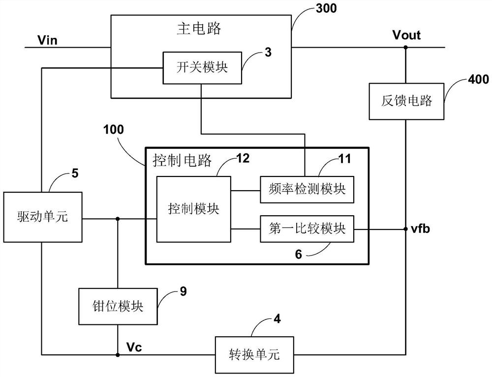
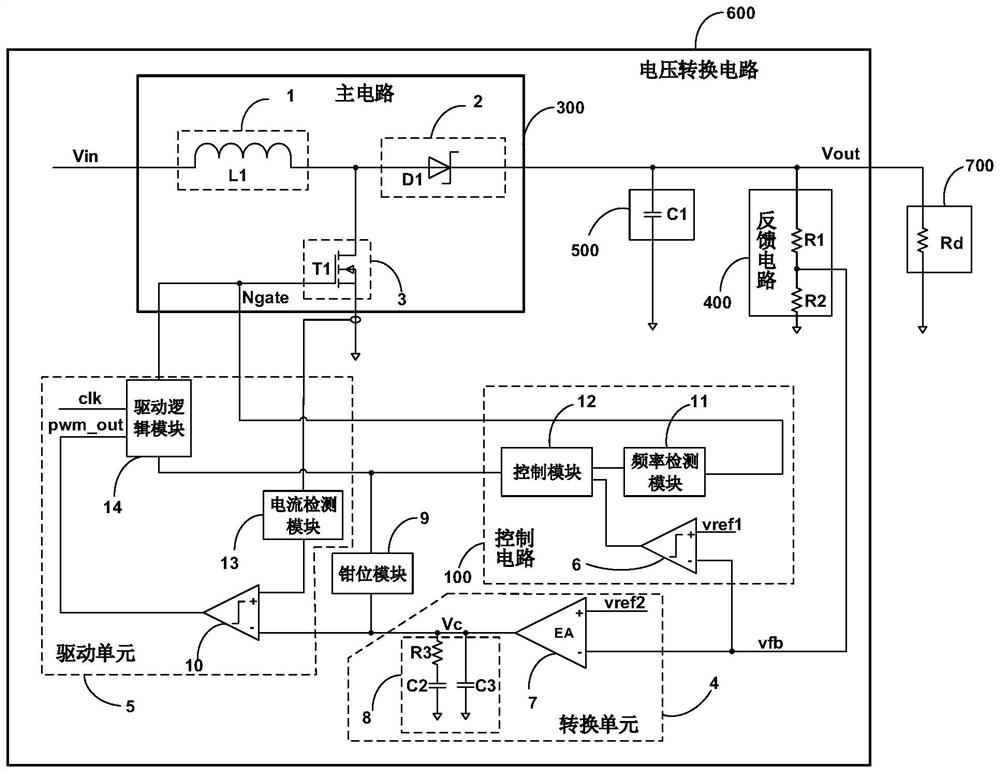
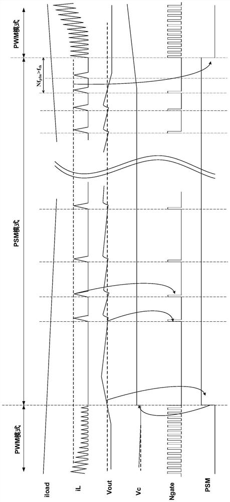
[0004] Aiming at the shortcomings of the existing methods, the present application proposes a voltage conversion circuit and a power converter to solve the technical problem that the voltage conversion circuit in the prior art has low conversion efficiency of the power supply voltage under the condition of light load

Method used


Image

  • Voltage conversion circuit and power converter
  • Voltage conversion circuit and power converter
  • Voltage conversion circuit and power converter

Examples


Embodiment Construction

[0047] The present application is described in detail below, and examples of embodiments of the present application are shown in the drawings, wherein the same or similar reference numerals represent the same or similar components or components having the same or similar functions throughout. Also, detailed descriptions of known technologies will be omitted if they are not necessary to illustrate the features of the present application. The embodiments described below by referring to the figures are exemplary only for explaining the present application, and are not construed as limiting the present application.

[0048] Those skilled in the art can understand that, unless otherwise defined, all terms (including technical terms and scientific terms) used herein have the same meanings as commonly understood by those of ordinary skill in the art to which this application belongs. It should also be understood that terms, such as those defined in commonly used dictionaries, should ...


PUM


Abstract

The invention provides a voltage conversion circuit and a power converter. The voltage conversion circuit comprises a main circuit, a feedback circuit, a control circuit, a clamping module and a driving unit, the control circuit is connected with the driving unit and the clamping module and is used for comparing the feedback voltage with the first reference voltage and outputting a second signal when the feedback voltage is higher than the first reference voltage; the clamping module is used for boosting the first voltage converted based on the feedback voltage and fixing the first voltage to a first preset voltage based on the second signal; and the driving unit is electrically connected with the control end of the switch module and is used for adjusting the driving mode of the switch module into a pulse cross-period modulation mode based on the second signal and controlling the switch-on and switch-off of the switch module. Under the light load condition, the voltage conversion circuit is controlled to enter the pulse cross-period modulation mode, the switch module can be driven to be switched on and switched off at a low frequency, the power consumption of the switch module can be reduced, and the power supply voltage conversion efficiency can be improved.

Description

technical field [0001] The present application relates to the field of power supply technology, and in particular, the present application relates to a voltage conversion circuit and a power converter. Background technique [0002] A common voltage conversion circuit (for example, a DC-DC circuit) can provide a load with a stable output voltage by detecting the output voltage and using negative feedback. For example, in a pulse width modulation (PWM, Pulse Width Modulation) type DC-DC circuit, the on and off of the switch tube is driven by a square wave signal, and the output voltage of the DC-DC circuit is generally controlled by the square wave signal. The duty cycle of the wave signal is controlled. [0003] For a switch tube (for example, a MOS tube) in a voltage conversion circuit, a considerable part of power consumption is required for periodic charging and discharging to control switching of the switch tube. As the connected load decreases, the load current of the ...

Claims


Application Information

Patent Timeline
IPC IPC(8): H02M3/156H02M3/155H02M1/32G05F1/56
CPCH02M3/156H02M3/155H02M1/32G05F1/56
Inventor 李育军周拥华赵新江
Owner 베이징에스윈컴퓨팅테크놀로지씨오엘티디
Learn More