Rain sewage diversion device and method

A diversion device, rainwater and sewage technology, applied in water supply devices, sewage removal, water/sewage treatment, etc., can solve the problems of inability to effectively discharge sundries, unable to discharge all sundries, etc. Residual residue, high practical effect

Pending Publication Date: 2022-04-01
宏伟建设工程股份有限公司
View PDF1 Cites 0 Cited by
  • Summary
  • Abstract
  • Description
  • Claims
  • Application Information

AI Technical Summary

Problems solved by technology

[0006] The purpose of the present invention is to provide a rainwater and sewage diversion device and method to solve the problem that the inner bottom wall of the above background technology is horizontal, and the sundries on the inner bottom wall of the rain and sewage separation cylinder cannot be effectively discharged when the sundries are discharged. , at the same time, the inner bottom wall is integrated, which cannot make the internal sundries quickly and completely discharged, etc.

Method used


Image

  • Rain sewage diversion device and method
  • Rain sewage diversion device and method
  • Rain sewage diversion device and method

Examples


Embodiment 1

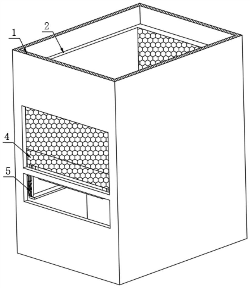
[0033] see figure 1 , figure 2 , Figure 4 to Figure 6 , the embodiment of the present invention provides a rain and sewage diversion device: including a housing 1 and a box 2 arranged in the housing 1, the size of the housing 1 and the box 2 are matched, and the rain and sewage flow from the top of the housing 1 Introduce and enter the inside of the box 2; both sides of the shell 1 are provided with a water outlet and a sundries outlet, and the water outlet is located above the sundries outlet. In order to facilitate the introduction of water and sundries, the external pipe can be connected The outlet is connected to the sundry outlet, and it is best to be inclined; the frame 2 is designed to penetrate up and down, and both sides of the frame 2 are provided with holes for water to pass through, and the bottom of the frame 2 is symmetrically arranged for The collection assembly 3 for collecting sundries, the collection assembly 3 includes a base plate 301, the base plate 30...

Embodiment 2

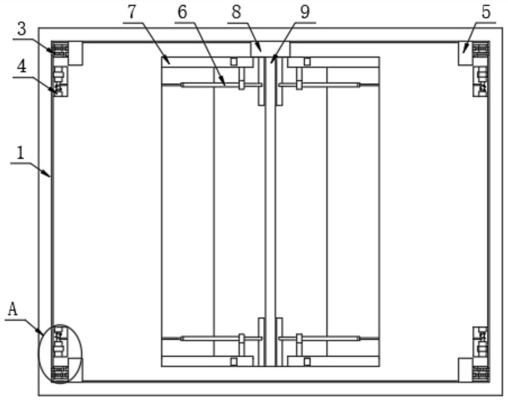
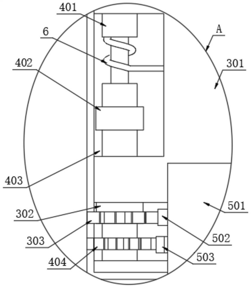
[0039] see Figure 1 to Figure 7 , on the basis of Embodiment 1, the collection assembly 3 also includes a hollow tube 302, the hollow tube 302 runs through the corner of the bottom plate 301 and is fixedly connected to it, the water permeable assembly 4 is rotatably arranged inside the hollow tube 302, and the outer surface of the hollow tube 302 A first gear 303 is fixedly installed in transmission connection with the transmission assembly 5 .

[0040] The water-permeable component 4 includes a central shaft 401 that is rotatably matched with the hollow tube 302. The central shaft 401 is rotatably sleeved inside the hollow tube 302. The end of the central shaft 401 is rotatably connected to the inner wall of the frame 2. The pillar 402 and the second gear 404 corresponding to the position of the transmission assembly 5 are fixedly installed. The side wall of the bottom plate 301 close to the central axis 401 is provided with a groove for accommodating the central axis 401 an...

Embodiment 3

[0047] see Figure 1 to Figure 10 , on the basis of Embodiment 2, inside the box 2 is a rectangular space, which can accommodate more sundries, and the rotation of the bottom plate 301 realizes that the sundries are conveyed in a fan-shaped trajectory, and the fan-shaped area is less than a quarter of a circle; When the discharge of rainwater and sewage is large and the sundries in the frame 2 accumulate too much, the rotation of the bottom plate 301 cannot realize the transportation of all the sundries in the box 2, and there may be some sundries from the two bottom plates 301 after rotation. The flow down in the middle will affect the normal use, so the second embodiment may not be effective when used when there are too many sundries.

[0048] The pusher assembly 6 includes two stay cords 601 arranged symmetrically. One end of the two stay cords 601 passes through the bottom plate 301 and is fixedly wound on the central shaft 401. The other ends of the two stay cords 601 are...


PUM


Abstract

The invention discloses a rain and sewage diversion device which comprises a shell and a square frame arranged in the shell, a water outlet and a sundry outlet are formed in the two sides of the shell in a penetrating mode, open holes for water to pass through are formed in the two sides of the square frame in a penetrating mode, and collecting assemblies for collecting sundries are symmetrically arranged at the bottom of the square frame. The collecting assembly comprises a bottom plate, permeable assemblies which are rotationally connected with the inner wall of the square frame and can allow water to pass through are rotationally installed on the two sides of the bottom plate, and an air cylinder used for driving the square frame to move along the shell is fixedly installed in the shell. Through cooperation of the collecting assembly, the transmission assembly, the water permeable assembly, the bottom plate and the like, effective separation of water and impurities can be achieved, the water permeable assembly and the bottom plate can be driven to rotate to form an obtuse angle, rapid flowing of the impurities is facilitated, all the impurities rapidly flow out of the impurity outlet, and the single-time discharge capacity is improved.

Description

technical field [0001] The invention relates to the technical field of rainwater and sewage diversion, in particular to a rainwater and sewage diversion device and method. Background technique [0002] During the daily rainfall process, the rainwater is often mixed with a certain amount of sundries and enters the pipeline from the discharge port. If the sundries in the rainwater are not treated, the normal discharge of the pipeline will be affected over time. [0003] Chinese Invention Patent Publication No. CN211228780U discloses a rain and sewage diversion and drainage device for urban underground, including a rain and sewage diversion main pipe and a rainwater diversion pipe and miscellaneous sewage diversion fixedly installed on the outer wall of the rain and sewage diversion main pipe The rainwater diversion pipe and the miscellaneous sewage diversion pipe all run through the rain and sewage diversion main pipe; it has the advantages of automatically discharging sundrie...

Claims


Application Information

Patent Timeline
Patent Type & Authority Applications(China)
IPC IPC(8): E03F1/00E03F5/04E03F5/06E03F5/14
Inventor 谢双林贺慧君黄棣巍
Owner 宏伟建设工程股份有限公司
Why Eureka
Try Eureka