
Modular manual ball valve

A manual ball valve, modular technology, applied in the direction of valve details, valve devices, engine components, etc., can solve problems such as troublesome operation, blockage of connection holes, etc., to reduce the difficulty of cleaning, facilitate multiple use, and improve smoothness Effect

Inactive Publication Date: 2022-04-01
ZHEJIANG YUANYAO VALVE IND
View PDF0 Cites 0 Cited by
  • Summary
  • Abstract
  • Description
  • Claims
  • Application Information

AI Technical Summary

Problems solved by technology

[0004] When most of the existing ball valves are used for a long time, the stains in the liquid transported will adhere to the inner wall of the connection hole of the ball, so that the accumulation of stains will cause the connection hole to be blocked for a long time and affect the supply. At the same time, the existing water spot cleaning method , it is necessary to disassemble the valve body and clean the inner wall of the ball, which is very troublesome to operate, so there is an urgent need for a ball valve that is easy to clean the inner wall of the ball

Method used


Image

  • Modular manual ball valve
  • Modular manual ball valve
  • Modular manual ball valve

Examples


Embodiment 1

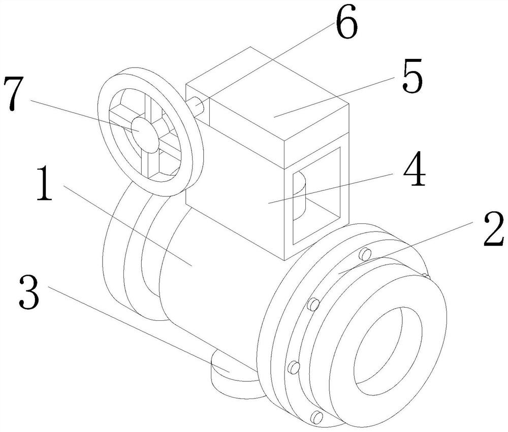
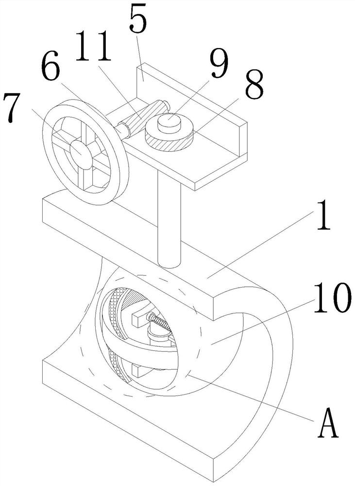
[0028] see Figure 1-6 , the present invention provides a technical solution: a modular manual ball valve includes a valve body 1, the left and right ends of the valve body 1 are provided with connecting flanges 2, when the device is used, it is connected to the water pipe through the connecting flange 2 , the bottom surface of the valve body 1 is fixedly connected with a bottom support 3, the top surface of the valve body 1 is fixedly connected with an internal hollow protective cover 4, the top surface of the protective cover 4 is fixedly connected with an internal hollow machine cover 5, the front of the machine cover 5 The surface is rotatably connected with a transmission rod 6, the rear end of the transmission rod 6 runs through the hood 5 and extends to the inside of the hood 5, the front end of the transmission rod 6 is fixedly connected with a hand wheel 7, when using the device, by turning the hand wheel 7 drives the transmission rod 6 to rotate.

[0029] Further, t...

Embodiment 2

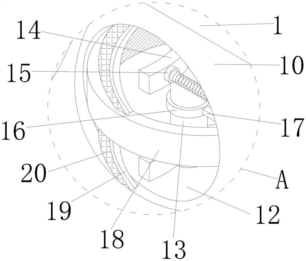
[0033] see Figure 1-6 , on the basis of Embodiment 1, the inside of the valve body 1 is provided with a swing device, the swing device includes a rotating shaft 13, the rotating shaft 13 is connected to the bottom surface of the inner wall of the water hole 12 in rotation, and the front surface of the rotating shaft 13 is fixedly connected with a guide The deflector 14 is fixedly connected with a spring 15 on the left surface of the deflector 14 , and the end of the spring 15 away from the deflector 14 is fixedly connected with the inner wall of the water hole 12 .

[0034] Further, when the device is used, when the water flow passes through the water hole 12, the driving force of the water flow is used to push the deflector 14 to rotate, and the rotation of the deflector 14 drives the rotation shaft 13 to rotate, and the deflector 14 is supported by the spring when it rotates. The limitation of 15 makes the deflector 14 unable to rotate substantially. After the water flow pa...


PUM


Abstract

The invention discloses a modular manual ball valve, and belongs to the technical field of ball valves. The modular manual ball valve comprises a valve body, connecting flanges are arranged at the left end and the right end of the valve body, a bottom support is fixedly connected to the bottom face of the valve body, a protective cover with the hollow interior is fixedly connected to the top face of the valve body, a machine cover with the hollow interior is fixedly connected to the top face of the protective cover, and a driven transmission rod is rotationally connected to the front surface of the machine cover; the rear end of the transmission rod penetrates through the machine cover and extends into the machine cover, the front end of the transmission rod is fixedly connected with a hand wheel, a swing device is arranged in the valve body, and a decontamination device is arranged in the valve body. Through the arrangement of the decontamination device, the swing device drives the decontamination device to do reciprocating motion, so that the cleaning plate repeatedly cleans the inner wall of the water through hole, water spots on the inner wall of the water through hole are reduced, the water spots are prevented from blocking the water through hole, and the smoothness of water flow is improved.

Description

technical field [0001] The invention belongs to the technical field of ball valve equipment, and in particular relates to a modular manual ball valve. Background technique [0002] Ball valve (ball valve), the opening and closing part (ball) is driven by the valve stem and rotates around the ball valve axis. There is a strong shear force between the metal valve seats of the cemented carbide, which is especially suitable for media containing fibers and tiny solid particles. [0003] The multi-way ball valve can not only flexibly control the confluence, diversion, and switching of the flow direction of the medium on the pipeline, but also can close any channel to connect the other two channels. This type of valve should generally be installed horizontally in the pipeline. The ball valve is in accordance with The drive mode is divided into: pneumatic ball valve, electric ball valve, manual ball valve. [0004] When most of the existing ball valves are used for a long time, th...

Claims


Application Information

Patent Timeline
Patent Type & Authority Applications(China)
IPC IPC(8): F16K5/08F16K31/53F16K31/60B08B1/04
Inventor 黄云明寿剑飞周炳
Owner ZHEJIANG YUANYAO VALVE IND
Learn More