Supercharge Your Innovation With Domain-Expert AI Agents!

Image decoding device, image decoding method, and program

An image decoding, half-pixel technology, applied in image communication, digital video signal modification, electrical components, etc.

Pending Publication Date: 2022-04-01
KDDI CORP
View PDF0 Cites 0 Cited by
  • Summary
  • Abstract
  • Description
  • Claims
  • Application Information

AI Technical Summary

Problems solved by technology

[0004] Although both are applicable to the case where the reference target of mv is at the position of decimal pixel precision, the above smoothing filter is only limited to the case where the reference target of mv is at the position of 1 / 2 pixel precision, and it is only suitable for displaying half-pixel index (hereinafter referred to as In the case where hpelIfIdx) is valid, the half-pixel index indicates whether the above-mentioned smoothing filter is valid

Method used


Image

  • Image decoding device, image decoding method, and program
  • Image decoding device, image decoding method, and program
  • Image decoding device, image decoding method, and program

Examples


no. 1 approach >

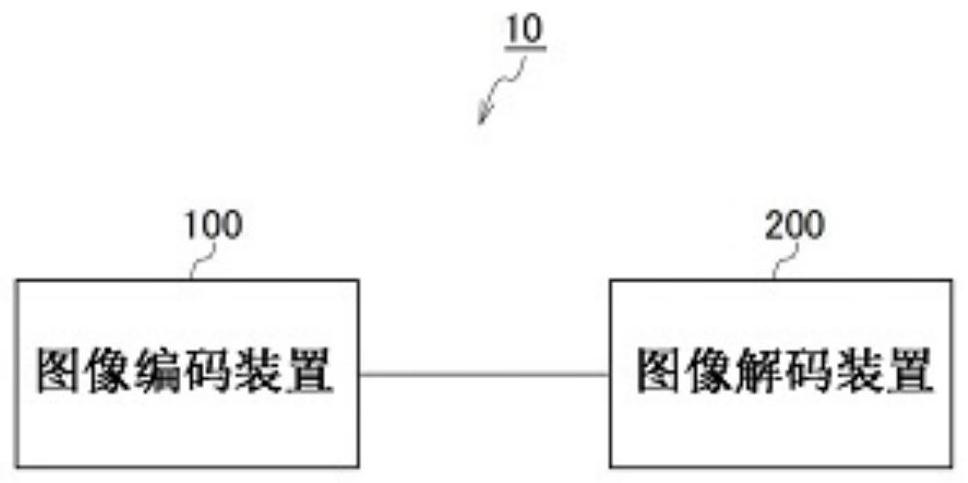
[0052] Below, refer to Figure 1 to Figure 28 The image processing system 10 according to the first embodiment of the present invention will be described. figure 1 It is a figure which shows the image processing system 10 of this embodiment.

[0053] Such as figure 1 As shown, the image processing system 10 of this embodiment includes an image encoding device 100 and an image decoding device 200 .

[0054] The image encoding device 100 is configured to generate encoded data by encoding an input image signal. The image decoding device 200 is configured to generate an output image signal by decoding encoded data.

[0055] The encoded data can be sent from the image encoding device 100 to the image decoding device 200 via a transmission path. The encoded data may also be supplied from the image encoding device 100 to the image decoding device 200 after being stored in a storage medium.

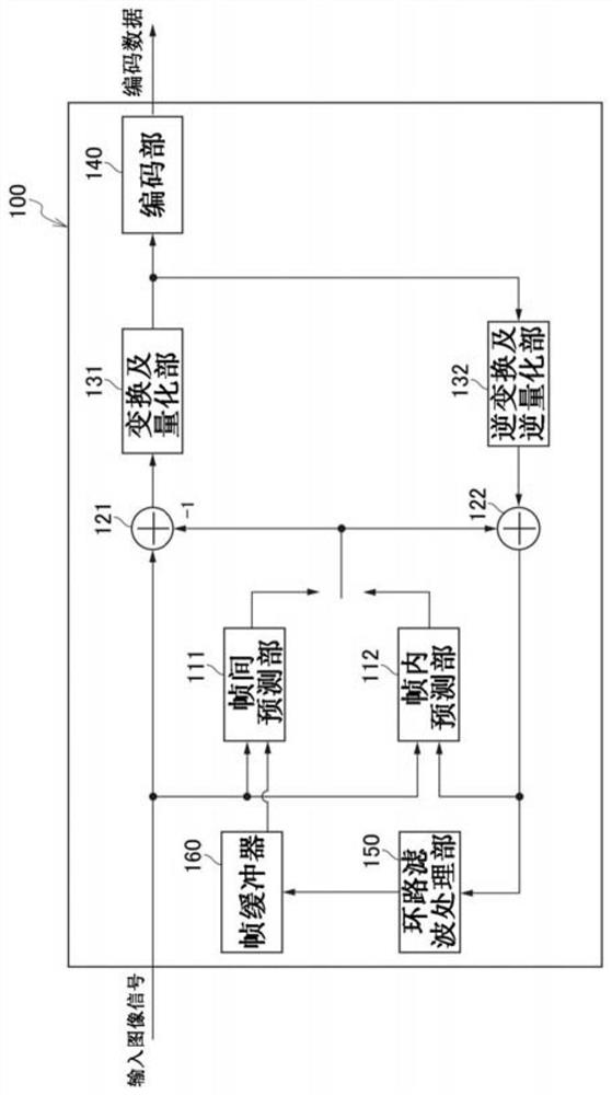
[0056] (Image coding device 100)

[0057] Below, refer to figure 2 The image encoding...

change example

[0253] [Changed example: Modification of rounding processing related to MMVD]

[0254] Next, a modification of the rounding process of mv when mv is corrected by MMVD shown in step S23-3 above will be described.

[0255] The above method is to directly round the mv after applying MMVD to the position of 1 / 2 pixel precision, but as the first alternative method, it is also possible to round the mvd when applying MMVD to the position of 1 / 2 pixel precision, indirectly Round the mv after applying MMVD.

[0256] For example, consider the Figure 24 The method for making changes to a table, the Figure 24 The table of shows the offset value of mvd corresponding to mmvd_distance_idx. Specifically, consider the following two approaches.

[0257] The first method is to add the judgment of hpelIfIdx to Figure 24 Ideas in the table. exist Figure 25 In , the table after adding the judgment of hpelIfIdx is shown.

[0258] exist Figure 24 In the conventional table shown, the off...


PUM


Abstract

This image decoding device (200) is provided with: a merge unit (241A2) that decodes a motion vector and a half-pixel index on the basis of a merge index; a motion vector refinement unit 241B that refines the motion vector by MMVD or DMVR; a filter determination unit 241C1 that determines whether or not to use an interpolation filter and an interpolation filter type on the basis of the refined motion vector and the half-pixel index; and a filter application unit (241C2) that generates a motion-compensated prediction pixel signal using an interpolation filter. Furthermore, a merging unit 241A2 generates a merge list by a specific merge list construction method, and decodes the motion vector and the half-pixel index on the basis of the merge list and the merge index.

Description

[technical field] [0001] The invention relates to an image decoding device, an image decoding method and a program. [Background technique] [0002] In Non-Patent Document 1, there are motion compensation prediction (hereinafter referred to as MC prediction) technologies for deriving motion vectors (hereinafter referred to as merge coding) and adaptive vector coding (hereinafter referred to as AMVP). Hereinafter, the technique is referred to as mv), and two types of interpolation filters for generating an MC prediction image signal using the derived mv are prepared. [0003] The first type is the same interpolation filter as in Non-Patent Document 2 (hereinafter referred to as HEVC filter), and the second type is an interpolation filter newly introduced in Non-Patent Document 1 (hereinafter referred to as a smoothing filter). [0004] Although both are applicable to the case where the reference target of mv is at the position of decimal pixel precision, the above smoothing f...

Claims


Application Information

Patent Timeline
Patent Type & Authority Applications(China)
IPC IPC(8): H04N19/52H04N19/117H04N19/139H04N19/513H04N19/105H04N19/523H04N19/59H04N19/176
CPCH04N19/105H04N19/523H04N19/513H04N19/117H04N19/139H04N19/52H04N19/59H04N19/176
Inventor 木谷佳隆海野恭平河村圭内藤整
Owner KDDI CORP
Features
  • R&D
  • Intellectual Property
  • Life Sciences
  • Materials
  • Tech Scout
  • Unparalleled Data Quality
  • Higher Quality Content
  • 60% Fewer Hallucinations
Learn More