Multifunctional retraction fixator

A retainer and multi-functional technology, applied in the field of medical equipment, can solve the problems of difficult manufacturing technology of the retainer ring, difficulty of the retainer, and low firmness, so as to save medical labor, save operation time, and avoid secondary injuries. Effect

Pending Publication Date: 2022-04-05
微至(苏州)医疗科技有限公司
View PDF0 Cites 0 Cited by
  • Summary
  • Abstract
  • Description
  • Claims
  • Application Information

AI Technical Summary

Problems solved by technology

This kind of fixing ring is difficult to manufacture and has low firmness. It is difficult to cooperate with the retractor, and there is a possibility of loosening

Method used


Image

  • Multifunctional retraction fixator
  • Multifunctional retraction fixator
  • Multifunctional retraction fixator

Examples


Embodiment 1

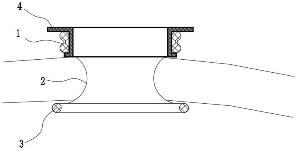
[0036] A multifunctional retractor, comprising an outer ring 1, a channel membrane 2 and an inner ring 3, the material of the channel membrane 2 is added with a developer, and the preparation process of developing the channel membrane, in the existing common channel membrane material, adding Developers, such as barium sulfate, bismuth trioxide, bismuth subcarbonate, iodine-containing polymethacrylate and one or several composite developers, the addition amount is between 1% and 15%. Sharp instruments have defects that are difficult to find when the channel membrane is punctured and dropped into the abdominal cavity. By developing the channel membrane, CT and X-ray films can be used to find the channel membrane fragments remaining in the human body.

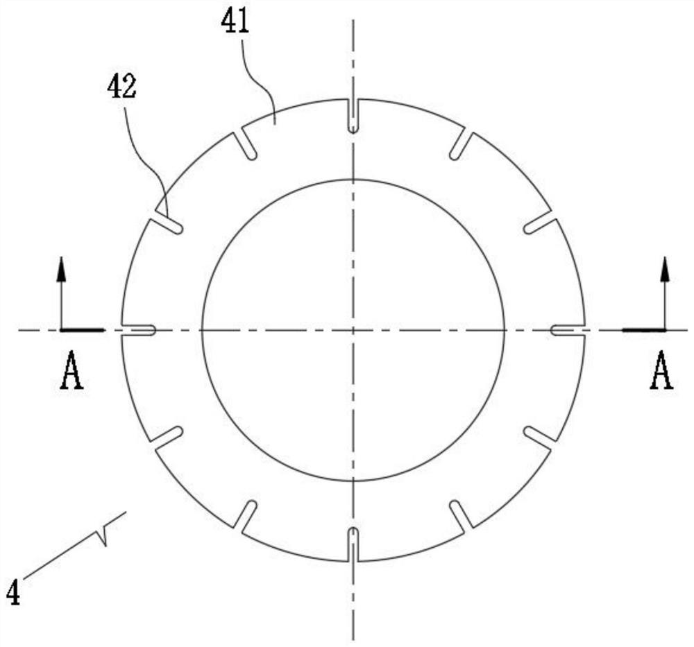
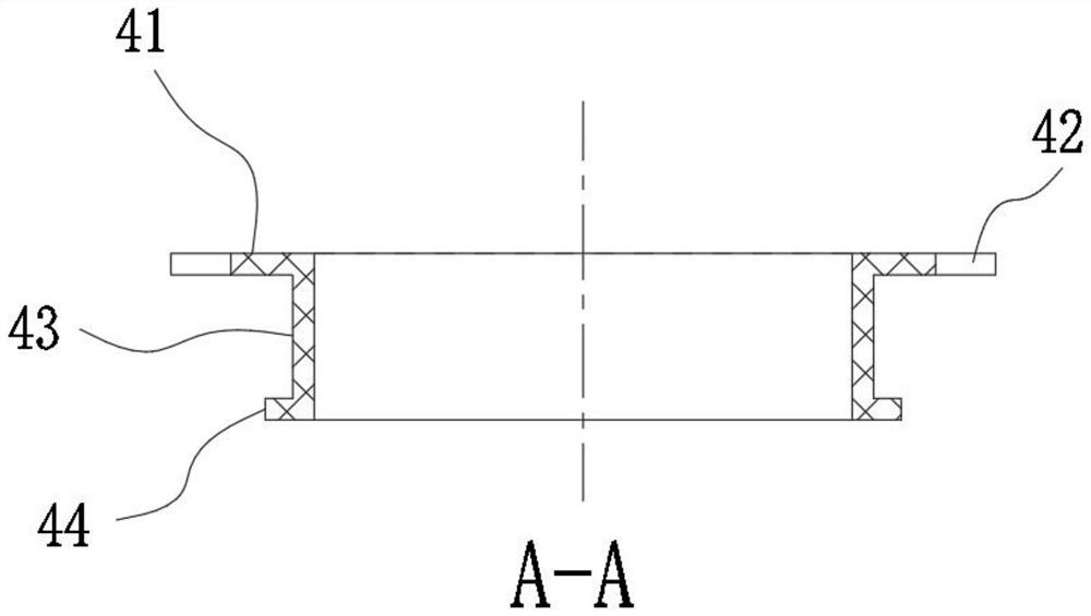
[0037] The outer ring 1 is clamped with a rigid ring 4. The rigid ring 4 includes a ring body 43 placed in the outer ring 1. The ring body 43 is circular. The upper eaves 41 and the lower eaves 44 are formed. The end surface of th...

Embodiment 2

[0042] The difference from Embodiment 1 is that the draw-in groove 42' is a plurality of sets of arc-shaped grooves, and is combined into a ring on the end surface of the upper eaves 41, and the ring formed by the draw-in groove 42' is concentric with the upper eaves 41, and the endoscope holder 5 also passes The connecting rod 52 is snapped into the slot 42'.

Embodiment 3

[0044] The difference from Embodiment 1 is that the limiting part 53' is a ring, and the upper end of the rigid ring 4 is fixed with a buckle 46 with the same inner diameter as the ring body 43. The buckle 46 is connected with the ring body 43, and the outer wall is provided with a buckle Groove 45, the limiting part 53' is clamped in the buckle groove 45, the fixing part 51 and the limiting part 53' are arranged on the same plane, and the fixing part 51 can also be at other angles to realize the limiting of the endoscope. This embodiment Among them, the end face of the upper eaves 41 does not need to offer a draw-in groove.


PUM


Abstract

Developing agents are added into a channel film material, a rigid ring is clamped in an outer ring and comprises a ring body arranged in the outer ring, the outer walls of the upper end and the lower end of the ring body are provided with a circular upper brim and a circular lower brim which expand in the radial direction of the ring body respectively, a clamping groove is formed in the end face of the upper brim, and a clamping groove is formed in the end face of the lower brim. A detachable endoscope fixer is arranged on the rigid ring, and the endoscope fixer comprises a fixing part connecting rod and a limiting part. The invention relates to the technical field of medical instruments. By arranging the channel membrane capable of being developed, it is convenient to find that fragments of the channel membrane stay in the human body, and secondary injury to a patient caused by infection or body rejection reaction is avoided. By arranging the rigid ring, enough supporting force is provided, the operation view of a doctor is expanded, and the operation time is saved. By arranging the endoscope fixing device, the two hands are liberated, medical labor is saved, and medical workers are more focused on the illness state of the patient.

Description

technical field [0001] The invention relates to the technical field of medical devices, in particular to a multifunctional retractor fixer. Background technique [0002] Retractors are used in surgery. The existing retractor retainer channel membrane is too sharp, which has the defect that it is difficult to find the channel membrane and fall into the abdominal cavity; when performing small incision surgery, an additional assistant is required to hold the endoscope, which increases the manpower burden. The outer ring of the existing retractor fixator is not strong enough in clinical use, which leads to irregular shape of the retracted wound and limits the operation. [0003] At present, in order to increase the retraction strength of the outer ring, there are two schemes. One is to add hard wires such as steel wires in the hollow hole of the outer ring. Additional metal rakes are used to hook in two or four symmetrical directions to assist retraction. [0004] The existin...

Claims


Application Information

Patent Timeline
Patent Type & Authority Applications(China)
IPC IPC(8): A61B17/02
Inventor 刘安升张宁陈任寰何徐盛钱星宇
Owner 微至(苏州)医疗科技有限公司
Why Eureka
Try Eureka